I've been putting this off for some time because writing these posts takes a long time. I know the audience for this stuff is incredibly small, if it exists at all, but I hope to keep updating this as I learn more about the PIC32MZ.
Today I'm going to cover reading from and writing to an SD card in a mass storage device.
Read - Command 0x28
In a previous post I used DMA to read blocks from an SD card attached to SPI2. What I found was that when combined with a lot of interrupts and USB DMA it kept falling over, so I removed it. The good news is the new method is far more stable and just as fast. Let's take a look at the code:
case 0x28: // Read (10)
{
    if (MSD_ready)
    {
        read_length = (int)(cbw.CBWCB[7] << 8) | cbw.CBWCB[8];
        read_address  = (int)(cbw.CBWCB[2] << 24) | (int)(cbw.CBWCB[3] << 16) | (cbw.CBWCB[4] << 8) | (cbw.CBWCB[5]);

        blocks_left = read_length;
        toggle = 0;

        // Start SD multiblock read
        result = SD_start_multi_block_read(read_address);
        // Read first block
        addr = USB_data_buffer;
        result |= SD_read_multi_block(addr, 512);
        blocks_left--;

        // Wait until we are ready to send on EP1
        USB_EP1_wait_TXRDY();

        while (blocks_left)
        {
            // Send this block via DMA
            USB_EP1_DMA_DONE = 0;
            addr = USB_data_buffer + (toggle * 512);
            USB_EP1_send_DMA(addr, 512);

            // While it's sending, read the next block in
            toggle ^= 1;
            addr = USB_data_buffer + (toggle * 512);
            result |= SD_read_multi_block(addr, 512);

            // Wait until DMA transfer is done before continuing
            while (!USB_EP1_DMA_DONE);
            USB_EP1_wait_TXRDY();
            blocks_left--;
        }

        // Stop the SD card multiblock read
        SD_stop_multi_block_read();

        // There will be one block that is left unsent, send it now
        USB_EP1_DMA_DONE = 0;
        USB_EP1_send_DMA(addr, 512);
        while (!USB_EP1_DMA_DONE);
        USB_EP1_wait_TXRDY();

        if (result != RES_OK)
        {
            requestSenseAnswer[2] = 0x5;
            requestSenseAnswer[12] = 0x20;
            csw.dCSWDataResidue = 252;
            csw.bCSWStatus |= 1; // Error occurred
        }
    }
    else
    {
        csw.bCSWStatus |= 1; // Error occurred
        requestSenseAnswer[2] = 2;
    }

    break;

}
OK, it's not that long. Let's take a look at it bit by bit. Oh, and MSD_ready is a flag I use to signify if an SD card is attached.
read_length = (int)(cbw.CBWCB[7] << 8) | cbw.CBWCB[8];
read_address  = (int)(cbw.CBWCB[2] << 24) | (int)(cbw.CBWCB[3] << 16) | (cbw.CBWCB[4] << 8) | (cbw.CBWCB[5]);
The host will send us the amount of blocks (that is, 512-byte blocks on an SD card), to read as well as the Logical Block Address (LBA) to start reading at.
For the rest of it, instead of line by line I think it'd be better to explain what it's doing. The way I have implemented the reading system is to first initiate a multi-block read (SD_start_multi_block_read()) from the SD card. You do this by sending it a special command (CMD18) along with the starting address. If you are reading many blocks, this works out much faster than reading multiple single blocks.
Once I have done this, I read 512 bytes from the SD card (SD_read_multi_block()) and send it to the host via USB DMA (USB_EP1_send_DMA()) and immediately start reading another block from the SD card. In this way the amount of time the SD card is idle and the amount of time the USB transfer is idle is greatly reduced.
I've also implemented a double-buffer system so that when I'm reading I can send at the same time. In this way, I can read large 64kB blocks from the SD card and send them to the host at a fairly high speed while only using 1kB of RAM.
On reasonably good SD cards, I've managed transfer speeds of 5.5MB/s, which is way faster than the 2MB/s I was getting from Harmony.
USB DMA
The USB peripheral on the PIC32MZ has its own DMA system, separate from the DMA system I covered before. In the previous section I talked about sending blocks via DMA, let's take a quick look at how this would look:
void USB_EP1_send_DMA(unsigned char *buffer, uint32_t dmaCount)
{
    USB_EP1_DMA_DONE = 0;                           // Flag to indicate transfer is done

    USBE1CSR0bits.MODE = 1;                         // Set the mode to transfer (for receiving data, it'd be set to 0)

    USBDMA1Abits.DMAADDR = virt_to_phys(buffer);    // Set the address of the buffer to read from
    USBDMA1Nbits.DMACOUNT = dmaCount;               // Set the number of bytes to receive
    USBDMA1Cbits.DMABRSTM = 3;                      // Set DMA burst mode 3
    USBDMA1Cbits.DMAMODE = 0;                       // Set DMA mode 0
    USBDMA1Cbits.DMAEP = 1; // OUT Endpoint 1       // Set USB DMA channel 1 to work with endpoint 1
    USBDMA1Cbits.DMADIR = 1;                        // Set the DMA direction to transfer (again, for receiving you'd set this to 0)
    USBDMA1Cbits.DMAIE = 1;                         // Enable the USB DMA interrupt
    USBDMA1Cbits.DMAEN = 1;                         // Enable USB DMA channel 1
}
As with all DMA, you must declare the buffer "coherent", like this:
unsigned char __attribute__ ((coherent, aligned(8))) USB_data_buffer[USB_DATA_BUFFER_SIZE];
If you just declare it as always, that is:
unsigned char USB_data_buffer[USB_DATA_BUFFER_SIZE];
then your DMA transfers will not work.
Write - Command 0x2A
Let's take a look at the code first:
case 0x2A: // Write (10)
{
    if (MSD_ready)
    {
        read_length = (int)(cbw.CBWCB[7] << 8) | cbw.CBWCB[8];
        read_address  = (int)(cbw.CBWCB[2] << 24) | (int)(cbw.CBWCB[3] << 16) | (cbw.CBWCB[4] << 8) | (cbw.CBWCB[5]);

        USBCSR3bits.ENDPOINT = 2;

        blocks_left = read_length;

        while (blocks_left > 0)
        {
            if (blocks_left > USB_DATA_BUFFER_SIZE / 512)
                blocks_to_read = USB_DATA_BUFFER_SIZE / 512;
            else
                blocks_to_read = blocks_left;

            for (cnt = 0; cnt < blocks_to_read; cnt++)
            {
                while (!USBE2CSR1bits.RXPKTRDY)
                addr = USB_data_buffer + (512 * cnt);
                USB_EP2_DMA_DONE = 0;
                USB_EP2_receive_DMA(addr, 512);
                while (!USB_EP2_DMA_DONE);
                USBE2CSR1bits.RXPKTRDY = 0;
                blocks_left--;
            }

            result = disk_write(0, USB_data_buffer, read_address, blocks_to_read);
            result = RES_OK;

            read_address += (blocks_to_read * 512);

            if (result != RES_OK) csw.bCSWStatus |= 1; // Error occurred
        }
    }
    else
    {
        csw.bCSWStatus |= 1; // Error occurred
        requestSenseAnswer[2] = 2;
    }

    break;

}
When reading worked so well, I felt sure that I could do writing in a similar way. That is, read 512 bytes from the USB host and write them while simultaneously reading another 512 bytes from the host via DMA. However, when I tried this I had terrible writing speeds. At 2MB/s it was still double Harmony, but I was sure I could do better.
What I found was that reading the entire (up to) 64kB of data into a buffer and then writing it in one shot ended up way faster. I can now get consistent 4MB/s writes over USB, which makes the writing actually useful for many projects.
Writing to the SD card
I had never implemented SD card writing before, I was using ancient code I found almost 10 years ago online. It turns out multiblock writing is not terribly hard. Here's the code:
static
int xmit_datablock (    /* 1:OK, 0:Failed */
    const BYTE *buff,   /* 512 byte data block to be transmitted */
    BYTE token,         /* Data token */
    UINT count
)
{
    static BYTE resp;
    UINT bc = 512;

    // Clear out SPIBUF
    while (SPI_CHAN_FUNC(STATbits).RXBUFELM > 0)
    {
        resp = SPI_CHAN_FUNC(BUF);
        bc = resp;
    }

    if (wait_ready() != 0xFF) return 0;

    xmit_spi(token);        /* Xmit a token */
    if (token != 0xFD)
    {   /* Not StopTran token */

        // Send 16 bytes first
        for (bc = 0; bc < 16; bc++)
        {
            SPI_CHAN_FUNC(BUF) = *buff++;
        }

        bc = 512 - 16;

        while (bc > 0)
        {
            if (SPI_CHAN_FUNC(STATbits).RXBUFELM > 0)
            {
                // Read an 0xFF
                resp = SPI_CHAN_FUNC(BUF);
                // Send next byte
                SPI_CHAN_FUNC(BUF) = *buff++;
                bc--;
            }
        }

        while (SPI_CHAN_FUNC(STATbits).SPIBUSY);


        // Clear out the FIFO

        while (SPI_CHAN_FUNC(STATbits).RXBUFELM > 0)
        {
            resp = SPI_CHAN_FUNC(BUF);
        }

        // Get 2x CRC and 1x response
        SPI_CHAN_FUNC(BUF) = 0xFF;
        SPI_CHAN_FUNC(BUF) = 0xFF;
        SPI_CHAN_FUNC(BUF) = 0xFF;
        while (SPI_CHAN_FUNC(STATbits).SPIBUSY);
        while ((SPI_CHAN_FUNC(STATbits).RXBUFELM > 0))
        resp = SPI_CHAN_FUNC(BUF);

        if ((resp & 0x1F) != 0x05)  /* If not accepted, return with error */
            return 0;
    }


    return 1;
}
- Send CMD25 (multiple block write) and the starting address
- With each 512-byte block, wait until the SD card sends you 0xFF in return, indicating it is idle / ready
- Then write the token 0xFC before writing the data, which you can write immediately
- After you write the data, the SD card controller will send you 2 bytes of CRC and one byte of response data. If the lower 4 bits of the response are equal to 0x5, the write was successful, otherwise it failed
- After the last block has been written, send the token 0xFD to the SD card to indicate the multiblock write is done
The biggest change I made was that I made use of the Enhanced Buffers (ENHBUF) mode of SPI, enabling me to queue up to 16 bytes at once. This vastly reduced the amount of time the SPI port (and thus the SD card) were idle, and sped up transfers.
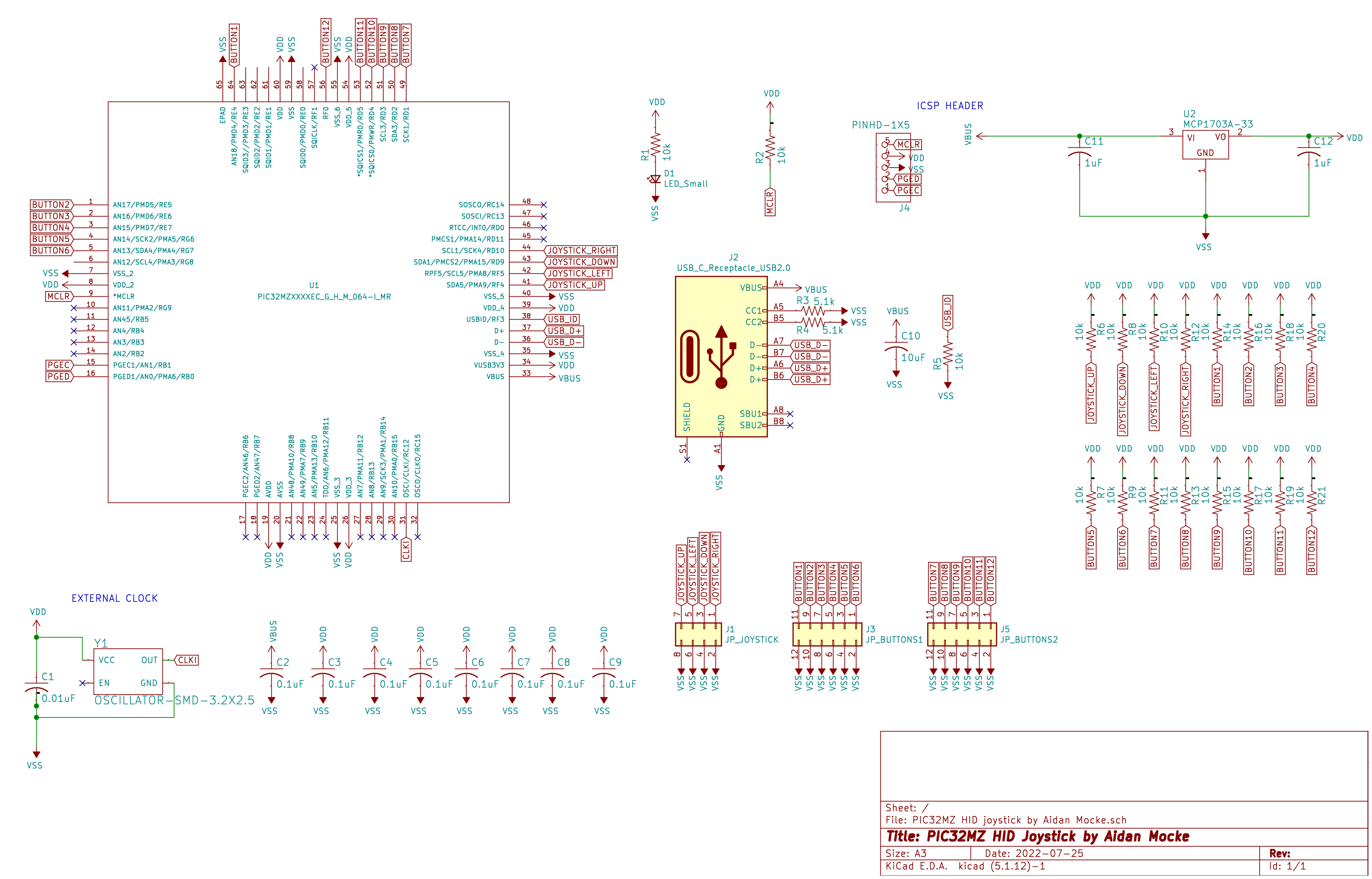
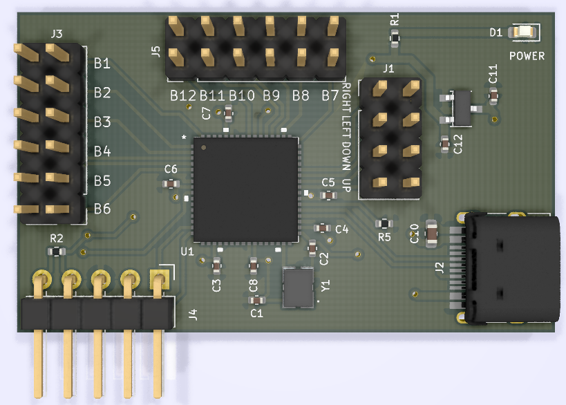
OK, long enough for one day. Next time I'll have a look at USB HID (keyboard) and show how I used it to make a joystick.