How to make a USB Mass Storage Device part 1 post
When writing my code the biggest problem I ran across was a lack of documentation on any of the things I needed to know. I found bits and pieces here and there on many, many sites but there was no one site I could go have a look at for a quick reference. So today, I'm going to explain the commands that you need to support, exactly what they mean and what the data structures you need to have look like.
In other words, extremely tl;dr. If you just want some code that worked for me (and hopefully will for you too!) check yesterday's post.
For today's post, I am assuming we want to use an SD card attached to a PIC32MZ as a Mass Storage Device.
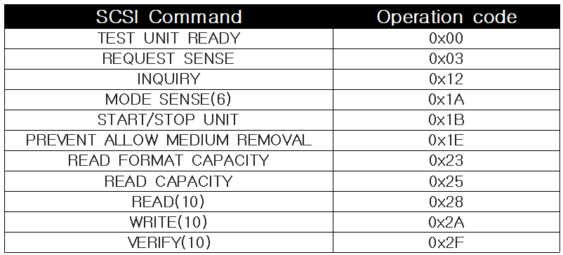
SCSI Transparent Command Set
Small Computer Systems Interface (SCSI) Primary Commands-2 (SPC-2) is a standard used to connect hard drives and optical drives to a computer. So why care? Because the USB Mass Storage Device (hereafter MSD) code we will be writing makes use of these commands, or rather a reduced set of them (thankfully) called the SCSI Transparent Command Set. The commands are as follows:
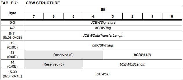
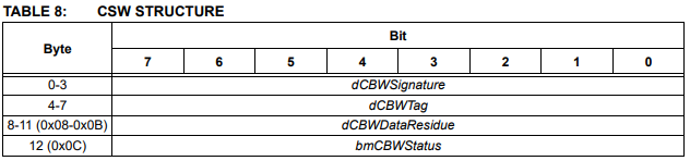
OK. Before going into what each of those mean, let's take a look at how these commands are sent to us. Each of these commands come to you in structured called a Command Block Wrapper (CBW) and after dealing with them you need to send back another structure called a Command Status Wrapper (CSW) to the host. So let's take a look at what the CBW and CSW look like:
(Images copied from Microchip's AN2554 app note)
Command Block Wrapper format
Command Status Wrapper format
So what'll happen is the host will issue a command, for example Read. You process the command and then send back a CSW.
A brief note on error handling
Before proceeding, it is important to understand how error handling works because it is also how we tell the host we don't support certain commands. So let's take an example. The host asks us to read some data and while we are performing the read operation an error occurs. What does this look like?
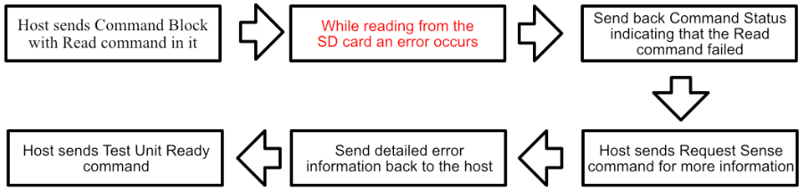
So either when something goes wrong or we don't support a command, it is not enough to send back an error in the CSW. The host will ask what the error was by sending a Request Sense command which we then have to reply to. Only then is the error handling process finished!
This is extra important because you must use this method to tell the host that you don't support certain commands (like Write, if you want a read-only device)!
Back to those SCSI Commands
OK, with that out the way, let's look at the 11 commands one by one and what replies we are expected to send for each.
Test Unit Ready Command 0x0
This command, as the name suggests, means the host is asking us to check if our connected SD card is attached and ready for reading and writing. If the card is ready, simply send back a Command Status Wrapper (hereafter CSW) with a bmCBWStatus of zero, indicating no error. If, however, the card isn't ready (for example, isn't attached yet), you can set the bmCBWStatus to 1 and also get ready for the host to issue a Request Sense command asking what exactly the error is. More info on that in the Request Sense command explanation, which is next.
Request Sense Command 0x3
The host sense the Request Sense command when you have previously send back a CSW with a bmCBWStatus value of anything but 0. In the status field, 1 is used to represent "Command failed" and 2 is used to represent "Phase error". To oversimplify, for Command failed, the host will reset the current operation and for Phase Error, which usually means the device has an irrecoverable error, the host will issue a Reset command to the device.
Anyway! The Request Sense command is used for the host to get detail information about what error has occurred, and it requires that you send back a fixed-format structure that looks like this:
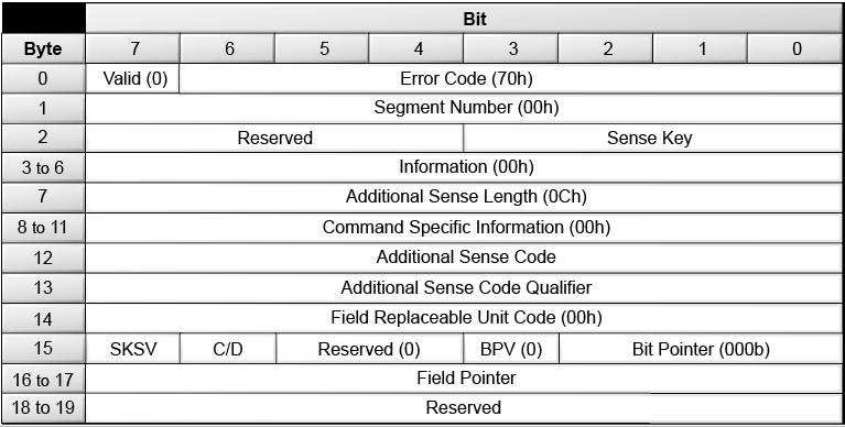
(This image copied from https://docs.oracle.com/en/storage/tape-storage/storagetek-sl150-modular-tape-library/slorm/img/slk_117.png)
OK wow that's a lot of extra stuff! Fortunately, you don't need to mess with any of it, except for the Sense Key and the Additional Sense Code fields. For a detailed look at all the error codes possible, head over to This excellent site on oracle.com.
For my code, however, it was enough to do the following:
- When there was a command I didn't support, set the Sense Key field to 0x5, which is "Illegal Command" (aka Unsupported Command)
- When there was an error with reading or writing, I set the Sense Key field to 0x2, which is "Not ready" and the Additional Sense Code field to 0x01 which is "In Process of Becoming Ready"
- When the SD card was not attached, I set the Sense Key field to 0x2 and the Additional Sense Code field to 0x1
Inquiry Command 0x12
This command is for the host to find out information about our device. We send back a fixed-format structure, again, that looks like this:
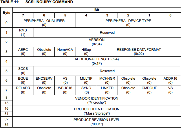
(Image copied from Microchip's AN2554 app note)
You need to set Peripheral Device Type to 0, indicating a device that has direct block access. That is, Windows (or whatever the host is) will tell you specifically which blocks to read and write from. Apart from that, there's not much we need to change here apart from the Vendor Identification, Product Identification and Product Revision Level fields.
Mode Sense(6) Command 0x1A
The Mode Sense 6-byte command (so named because the CBW is 6 bytes long) is again a way for the host to get more specific information about our device. We need to send back a structure with the following format:
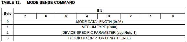
(Image copied from Microchip's AN2554 app note)
You can just reply with the values 3, 0, 0, 0 for our purposes.
Please note that I've read that Mac OS may instead issue a Mode Sense(10) Command (opcode 0x5A), which requires a slightly different 8 byte long structure in reply. I don't have a Mac so I can't test it but I believe the values 0,8,0,0,0,0,0,0 will work as a reply.
Start/Stop Unit Command 0x1B
This command only needs to be supported if you want to be able to eject your device from, for example, My Computer and have it disappear. There is no special reply required, just a CSW with a bmCSWStatus of 0.
Interestingly (well, interesting to me), many USB drives and Microchip Harmony do not seem to support this command (or at least Harmony v2.04 did not), which means you can "eject" them from Windows but they'll just stubbornly stay there in My Computer.
Prevent Allow Medium Removal 0x1E
This command caused me endless headaches. I implemented it at first and it all worked fine until it came to writing to my disk. You see, in Windows if you accept this command, Windows assumes your device will not suddenly be removed and therefore it caches everything it copies to the device. Why does this matter?
Well, if you're copying a 1GB file to the SD card, and it's writing at 2MB/s, it's going to naturally take a while. But the progress bar for the copy will immediately jump to 99% as Windows caches the entire copy and you will not be able to cancel the copy until it's done. Me, I like to see the progress bar. So what I had to do was, when this command came in, set bmCSWStatus to 1 (error) and set my Request Sense Sense Key to 0x5, Illegal Command.
Now that I don't support the command, Windows no longer assumes the drive won't suddenly disappear and doesn't enable write caching!
Read Format Capacity Command 0x23
This command requires us to send back a 12 byte array indicating the formatted capacity of our media. The format looks as follows:
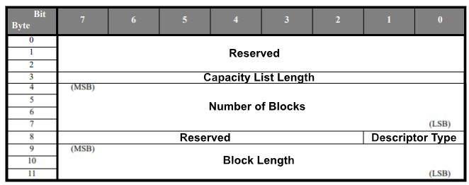
(Image taken from https://www.mikrocontroller.net/attachment/41812/0x23_READFMT_070123.pdf and edited a lot)
Let's take a look at this:
- The first 3 bytes must be 0, then the capacity list length must be set to 8.
- The next 4 bytes are an integer representing how many blocks we have on our SD card .
- Next is 1 byte representing the descriptor type. We set this to 2, formatted media.
- Then finally we have 3 bytes representing block length. For SD cards this is always 512 bytes!
However, we have an Endian problem here! Each of those groups of 4 bytes need to be put into reverse byte order! So for the first four bytes, you'd expect to send 0, 0, 0, 8 but in actuality you need to send 8, 0, 0, 0.
This command is also optional, and Harmony doesn't support it either. But it's so similar to the next command I supported it anyway.
Read Capacity Command 0x25
Very similar to the Read Format Capacity, except here we only send 8 bytes back:
- The first 4 bytes are the number of blocks on our device (blocks = sectors for our SD card)
- The last 4 bytes are the size of one sector (so 512 for our SD card example)
Like the Read Format Capacity command, the two groups of 4 bytes must be put into Little Endian order with the LSB first. So for "512" (which is 0x00000200 in hex) you actually need to send 0x00020000. A nice little trick to be aware of.
Read(10) Command 0x28
This command instructs us to read a certain amount of blocks (sectors)from the SD card and send them to the host. Again, a 10-byte Command Block will be sent from the host, hence the name. The flow of dealing with a read request looks like this:
- The host sends the number of the block you need to start reading on and the number of blocks to read in the CBW (this means that for an SD card, if the host asks you to read 3 blocks, it is expecting 3 x 512 bytes in return)
- Upon receipt of this instruction, immediately read from the SD card and send the data back to the host. You can read it all into a buffer and send it all back at once if you wish, the data will never be longer than 64kB per Read(10) request.
- Only after you have sent back all the data can you send a CSW indicating the operation was successful
Write(10) Command 0x2A
Very much like the Read(10) command except the flow is slightly different:
- The host sends the number of the block you need to start writing on and the number of blocks to write in the CBW
- The host immediately starts sending you the data you need to write. You can buffer this data and write it all at once later on, the data will never be longer than 64kB per Write(10) request.
- After sending all the data, send a CSW indicating success (or failure)
Verify Command 0x2F
This is a command for the host to ask the device to verify the data in a specified range of blocks. According to Microchip's AN282 app note, "this command is used when the host PC formats the filesystem". Honestly, by the time I got here I just wanted to get this code done and didn't implement it, instead just sending a "Passed" / "Good" status in the CSW.
However, for completeness, the host can either ask you to verify the data yourself and not send you any data to compare with, or it can send you the data it expects to be there so you can do a byte-by-byte comparison.
Overview
Phew that is extremely tl;dr, even for me and I can get pretty chatty. Next time, I'll start taking a look at how to implement this in code. Cheers for now!