USB descriptors and how to send and receive data on endpoint 0 post
Sending and receiving packets on Endpoint 0
Hello again. Last time we go to the point where we'd set up the USB peripheral, gotten a "Reset" command from the host and had set up our endpoints on the PIC32MZ side. Today I'll be briefly covering descriptors and how to send and receive data on endpoint 0 between the device and the host.
So let's take a look at the next step I have in my USB ISR:
    // Endpoint 0 Interrupt Handler
    if(USBCSR0bits.EP0IF == 1)
    {
        if(USBE0CSR0bits.RXRDY)
        {
            USB_receive_EP0(USBE0CSR2bits.RXCNT);

            USB_transaction.bmRequestType = EP[0].rx_buffer[0];
            USB_transaction.bmRequest = EP[0].rx_buffer[1];
            USB_transaction.wValue = (int)(EP[0].rx_buffer[3] << 8) | EP[0].rx_buffer[2];
            USB_transaction.wIndex = (int)(EP[0].rx_buffer[5] << 8) | EP[0].rx_buffer[4];
            USB_transaction.wLength = (int)(EP[0].rx_buffer[7] << 8) | EP[0].rx_buffer[6];

            USB_EP0_handle_transaction();

            if (USB_transaction.wLength == 0) USBE0CSR0bits.DATAEND = 1; // End of Data Control bit (Device mode)
        }

        if (USBE0CSR0bits.SETEND)
        {
            USBE0CSR0bits.SETENDC = 1;
        }

        USBCSR0bits.EP0IF = 0;  // Clear the USB EndPoint 0 Interrupt Flag.
    }
OK so it's not immediately obvious what's happening there, but broadly the steps are:
- If the EndPoint 0 Interrupt Flag
EP0IFis set inUSBCSR0that means something has occurred on endpoint 0 that we need to handle. - If the
RXRDYflag is set inUSBE0CSR0, that means we have received some data and need to read it out the FIFO. - We read the data and then process it to see what it being asked of us.
- We send a reply, if needed.
- We clear
EP0IFinUSBCSR0.
The number of bytes received is stored in USBE0CSR2bits.RXCNT. So let's take a look at how we read from the USB FIFO, because it has a nasty trap in it.
void USB_receive_EP0(int length)
{
    unsigned char *FIFO_buffer;
    int cnt;

    EP[0].rx_num_bytes = USBE0CSR2bits.RXCNT; // Endpoint 0 - Received Bytes Count

    FIFO_buffer = (unsigned char *)&USBFIFO0;

    for(cnt = 0; cnt < length; cnt++)
    {
        EP[0].rx_buffer[cnt] = *(FIFO_buffer + (cnt & 3)); // Store the received bytes in EP[0].rx_buffer[]
    }

    USBE0CSR0bits.RXRDYC = 1;
}
OK so it's fairly simple except for one thing:
    FIFO_buffer = (unsigned char *)&USBFIFO0;

    for(cnt = 0; cnt < length; cnt++)
    {
        EP[0].rx_buffer[cnt] = *(FIFO_buffer + (cnt & 3)); // Store the received bytes in EP[0].rx_buffer[]
    }
Why aren't we just reading from USBFIFO0 directly? Well, two reasons. First, any time you read from the USB FIFO buffers it is a 32-bit read. This means that if you just go:
data = USBFIFO0;
It will read 4 bytes from USBFIFO0 and clear them out of the FIFO, which is not at all what we want. So we have to access the FIFO indirectly, as an 8-bit byte, like this:
FIFO_buffer = (unsigned char *)&USBFIFO0;
We could read this 32-bits at a time, it'd seemingly be faster. But just like the other peripherals the 4 bytes you'd end up reading would be in the reverse order to what we wanted because the PIC32MZ uses Little Endian byte ordering, which means the byte order would be, for example, 3, 2, 1, 0, 7, 6, 5, 4 instead of the 0, 1, 2, 3, 4, 5, 6, 7 we expect. This means we'd have to do extra processing to get everything back in the order we want. Additionally, the length of all transactions isn't always divisible by 4 meaning yet more logic would be needed. And then finally, on the troubled PIC32MZ EC series, there is this nasty errata:
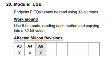
So, for now at least, I'm avoiding 32-bits. So we read it like this:
EP[0].rx_buffer[cnt] = *(FIFO_buffer + (cnt & 3)); // Store the received bytes in EP[0].rx_buffer[]
So what's going on there? We have an address pointed to by *FIFO_buffer. This address is the first byte of a 4-byte number. So to read all 4 bytes, we need to also read *FIFO_buffer + 1, *FIFO_buffer + 2 and *FIFO_buffer + 3. The moment we read from *FIFO_buffer + 3, the 4 bytes we just read will be cleared out of the FIFO buffer and a new value will appear in *USBFIFOA. So we need to start reading the first byte again (which is again *FIFO_buffer).
Next, let's take a look at this line:
USBE0CSR0bits.RXRDYC = 1;
What does it do? Let's play a game. Open up the PIC32MZ EF datasheet and search for "RXRDYC". I'll wait... Yeah, it's not there is it? And it isn't in DS60001326 either. But why? Let's follow the declaration in MPLAB X and see where it goes:
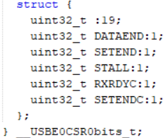
And let's compare that to the datasheet:
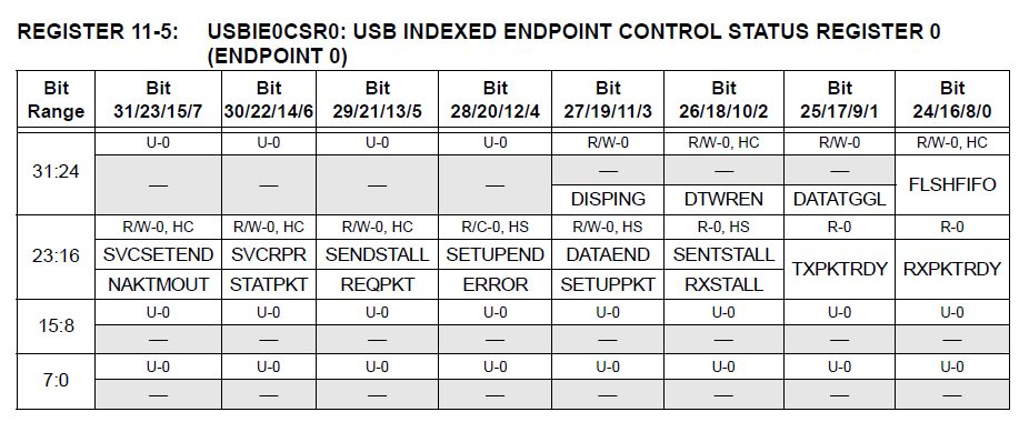
And before you ask yes, USBE0CSR0 and USBIE0CSR0 are referring to the same register. I don't know for sure what went wrong here but I guess it's just more proof that Microchip hates you and wants you to use Harmony. So anyway, the bit RXRDYC aka SVCRPR need to be set when we receive a packet. This in turn clear the bit field RXPKTRDY, which signifies that we got the packet. What?
- Setting RXRDYC clears RXPKTRDY (which we cannot clear directly for endpoint 0)
- Clearing RXPKTRDY means we received the packet successfully
OK finally, we have received a packet from the host. Now what do we do with it? Well, these so-called "setup packets" look like this:
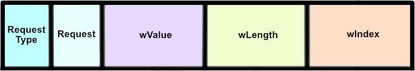
The important parts about this for us are:
- Request type's bit 7 will be set for a read request and cleared for a write request.
- Request is exactly what information the host wants from us.
- wValue is a parameter of request type (for specific requests within a certain type of request).
- wIndex is another parameter of request type.
- wLength is the maximum length of the reply that it expects.
That wLength can be pretty tricky. More on it later when we send descriptors.
In my code, I've retrieved these values like this:
USB_transaction.bmRequestType = EP[0].rx_buffer[0];
USB_transaction.bmRequest = EP[0].rx_buffer[1];
USB_transaction.wValue = (int)(EP[0].rx_buffer[3] << 8) | EP[0].rx_buffer[2];
USB_transaction.wIndex = (int)(EP[0].rx_buffer[5] << 8) | EP[0].rx_buffer[4];
USB_transaction.wLength = (int)(EP[0].rx_buffer[7] << 8) | EP[0].rx_buffer[6];
(Note: USB_transaction is just a struct I made myself to keep track of the current transaction)
OK so we have gotten our first packet. For my CDC example code, the first packet I get is:
80 06 00 01 00 00 40 00 (all numbers in hex)
Break that down we get:
- Request Type is 0x80 so it's an IN transmission, it wants us to send it something
- Request is 0x06, which is listed as "Get Descriptor"
- wValue is 0x0001, which means "Get Device Descriptor"
- wIndex is 0x0000, so nothing to see there
- wLength is 0x0040, meaning it wants a maximum of 64 bytes in return
OK so it wants our device descriptor. A descriptor is a set format for providing information about our device to the host computer. For my CDC example, my device descriptor looks like this:
unsigned char USB_device_description[] = {
/* Descriptor Length                        */ 18, /* Always 18 or 0x12 */
/* DescriptorType: DEVICE                   */ 0x01,
/* bcdUSB (ver 2.0)                         */ 0x00,0x02,
/* bDeviceClass                             */ 0x02,
/* bDeviceSubClass                          */ 0x00,
/* bDeviceProtocol                          */ 0x00,
/* bMaxPacketSize0                          */ 0x40, /* Always 64 or 0x40 for High Speed USB */
/* idVendor                                 */ 0xD8,0x04, /* e.g. - 0x04D8 - Microchip VID */
/* idProduct                                */ 0x0A,0x00, /* e.g. - 0x000A */
/* bcdDevice                                */ 0x00,0x02, /* e.g. - 02.00 */
/* iManufacturer                            */ 0x01,
/* iProduct                                 */ 0x02,
/* iSerialNumber                            */ 0x03,
/* bNumConfigurations                       */ 0x01
};
Each of these USB descriptors has a length byte in the front which is the total length of the descriptor. This is a pretty set format and if you change the wrong things you'll find the host (Windows or whatever) fails to recognise your device. But there are some things you can change here, namely:
/* bcdUSB (ver 2.0) */ 0x00,0x02,
This 0x0002 (which is actually going to be interpreted by the host as 0x0200) means our device supports USB specification version 2.00 (which is where High Speed USB came in).
/* idVendor                                 */ 0xD8,0x04, /* e.g. - 0x04D8 - Microchip VID */
/* idProduct                                */ 0x0A,0x00, /* e.g. - 0x000A */
/* bcdDevice - Device release number        */ 0x00,0x02, /* e.g. - 02.00 */
I've "borrowed" Microchip's USB vendor and product IDs because we are allowed to do so when testing our products using the PIC32. If you're going to release a commercial product you will naturally have to register with the USB Implementers Forum (USB-IF) and get your own codes.
/* iManufacturer                            */ 0x01,
/* iProduct                                 */ 0x02,
/* iSerialNumber                            */ 0x03,
These numbers are the index values of strings associated with manufacturer name, product name and product serial number. We will use these later. If you do not plan to provide these later you can safely set these to 0 and the host will not ask you for them later on.
OK, but how do we send this off to the host? Let's take a look:
// Send EP[0].tx_num_bytes from EP[0].tx_buffer on endpoint 0
void USB_send_EP0()
{
    int cnt;
    unsigned char *FIFO_buffer;

    FIFO_buffer = (unsigned char *)&USBFIFO0;

    if (USB_EP0_Wait_TXRDY()) return;

    cnt = 0;

    while (cnt < EP[0].tx_num_bytes)
    {
        *FIFO_buffer = EP[0].tx_buffer[cnt]; // Send the bytes
        cnt++;
        // Have we sent 64 bytes?
        if ((cnt > 0) && (cnt % 64 == 0))
        {
            // Set TXRDY and wait for it to be cleared before sending any more bytes
            USBE0CSR0bits.TXRDY = 1;
            if (USB_EP0_Wait_TXRDY()) return;
        }
    }

    if (cnt % 64 !=0 ) USBE0CSR0bits.TXRDY = 1;
}
So again, because we are sending a byte at a time, we need to get a byte sized pointer to USBFIFO0. There are, however, a few differences with sending and receiving. First off:
if (USB_EP0_Wait_TXRDY()) return;
We have to wait until the USB peripheral is ready to send a packet. The code of this function looks like this:
int USB_EP0_Wait_TXRDY()
{
    int timeout;

    timeout = 0;

    while (USBE0CSR0bits.TXRDY)
    {
        timeout++;
        if (timeout > USB_EP0_WAIT_TIMEOUT) return 1;
    };

    return 0;
}
When USBE0CSR0bits.TXRDY is set it means there is a packet in the FIFO buffer ready to send. Basically we need to wait until USBE0CSR0bits.TXRDY is clear before we're able to send another packet. Something I copied from MisterHemi's code is the timeout which will save us from being stuck in an infinite loop if the USB gets disconnected or something else goes wrong. In the datasheet, TXRDY is called TXPKTRDY so I don't know why they changed it. Amusingly (?), for all endpoints other than 0 it is still called TXPKTRDY. Go figure!
Furthermore, let's take a look at this section of the code:
if ((cnt > 0) && (cnt % 64 == 0))
{
    // Set TXRDY and wait for it to be cleared before sending any more bytes
    USBE0CSR0bits.TXRDY = 1;
    if (USB_EP0_Wait_TXRDY()) return;
}
The maximum size of a packet for endpoint 0 is 64 bytes (and I set it as much in the initialisation). But some data we need to send is more than 64 bytes long, so how do we do this? Well, we put 64 bytes into the FIFO buffer, set TXRDY to 1 to let the hardware know we have a packet it has to send, and then wait for TXRDY to be cleared. We repeat this every 64 byte chunk until we are finished. At the end we once again need to set TXRDY to tell the USB peripheral to send the data we put into the FIFO buffer, but only if we're not on another 64 byte boundary :)
OK, so that's the Device Descriptor sent, next it is going to ask us for...
The Configuration Descriptor
This is where the host is going to ask us for specifics about our USB device. What kind of device it is, how many endpoints it has, how many configurations it has, how much power it uses if bus powered (powered by the USB port) or if it is self-powered. It is pretty long and again, there's not much here you can freely change. This is what it looks like for my CDC device:
unsigned char USB_config_descriptor[] = {
// Referenced from: https://gist.github.com/tai/acd59b125a007ad47767
/*********************************************************************
 Configuration Descriptors
 *********************************************************************/
/*  bLength (Descriptor Length)             */ 9,    // How long is this initial descriptor?
/*  bDescriptorType: CONFIG                 */ 0x02  // What kind of descriptor is this? 0x02 = configuration descriptor
/*  wTotalLength                            */ 0x43,0x00, // What is the total length of this packet? (0x0043 = 67 bytes)
/*  bNumInterfaces                          */ 2,    // How many interfaces does this device have? 2
/*  bConfigurationValue                     */ 1,    // How many configurations does this device have?
/*  iConfiguration                          */ 0,    // String offset for the name of this configuration, I've elected to not provide a name so set this to 0
/*  bmAttributes                            */ 0x80, // bit 6 set = bus powered = 0x80, 0xC0 is for self powered. See important note below!
/*  bMaxPower                               */ 0x32, // Value x 2mA, set to 0 for self powered, was 0x32
/*********************************************************************
  Interface 0 - Communications Class
 *********************************************************************/
/* bLength                                  */ 0x09,
/* bDescriptorType: INTERFACE               */ 0x04,
/* bInterfaceNumber                         */ 0x00, // So as you can see, the interface numbers are zero-based
/* bAlternateSetting                        */ 0x00, // It has no alternate configurations
/* bNumEndpoints: 1 endpoint(s)             */ 0x01, // We have one endpoint for this interface
/* bInterfaceClass: CDC                     */ 0x02, // It is a CDC device
/* bInterfaceSubclass:Abstract Control Model*/ 0x02, // Using the Abstract Control Model (ACM)
/* bInterfaceProtocol:AT Commands V.25ter   */ 0x01, // Using AT Commands v.25ter
/* iInterface                               */ 0x00, // String offset = 0 again means no string
/*********************************************************************
 Header Functional Descriptor
 *********************************************************************/
/* bLength                                  */ 0x05,
/* bDescriptorType: CS_INTERFACE            */ 0x24,
/* bDescriptorSubtype: HEADER FD            */ 0x00,
/* bcdADC                                   */ 0x20,0x01,
/*********************************************************************
 Abstract Control Model Functional Descriptor
 *********************************************************************/
/* bLength                                  */ 0x04,
/* bDescriptorType: CS_INTERFACE            */ 0x24,
/* bDescriptorSubtype: ACM-FD               */ 0x02,
/* bmCapabilities                           */ 0x02,
/*********************************************************************
 Union Functional Descriptor
 *********************************************************************/
/* bLength                                  */ 0x05,
/* bDescriptorType: CS_INTERFACE            */ 0x24,
/* bDescriptorSubtype: Union FD             */ 0x06,
/* bControlInterface                        */ 0x00,
/* bSubordinateInterface                    */ 0x01,
/*********************************************************************
 Call Management Functional Descriptor
 *********************************************************************/
/* bLength                                  */ 0x05,
/* bDescriptorType: CS_INTERFACE            */ 0x24,
/* bDescriptorSubtype: CM-FD                */ 0X01,
/* bmCapabilities                           */ 0x00,
/* bDataInterface                           */ 0x01,
/*********************************************************************
 Interrupt IN Endpoint - 1 - IN means **to** the host **from** the device
 *********************************************************************/
/* bLength                                  */ 0x07,
/* bDescriptorType: ENDPOINT                */ 0x05,
/* bEndpointAddress: IN Endpoint 1          */ 0x81, // This is very important. 0x81 means endpoint 0x1 with an 0x80 ORed to it. Just writing 0x1 here would make it an OUT endpoint and you'd likely get a descriptor error from the host.
/* bmAttributes: INTERRUPT                  */ 0x03, // CDC needs one interrupt mode IN endpoint
/* max packet size (LSB)                    */ 0x10,
/* max packet size (MSB)                    */ 0x00, // The maximum size of this endpoint was set to 16 bytes in the endpoint initialisation, so we set it to 0x0010, which is 16
/* polling interval                         */ 0x2,  // A brief polling interval to ensure rapid checking
/*********************************************************************
 Interface 1 - Data Class Interface - The second interface of two
 *********************************************************************/
/* bLength                                  */ 0x09,
/* bDescriptorType: INTERFACE               */ 0x04,
/* interface index                          */ 0x01,
/* alt setting index                        */ 0x00,
/* bNumEndpoints: 2 endpoint(s)             */ 0x02, // This interface has two BULK mode endpoints attached to it
/* bInterfaceClass: CDC-Data                */ 0x0A,
/* bInterfaceSubclass: unused               */ 0x00,
/* bInterfaceProtocol: None                 */ 0x00,
/* iInterface                               */ 0x00,
/*********************************************************************
 Endpoint 2 (Bulk OUT)
 *********************************************************************/
/* bLength                                  */ 0x07,
/* bDescriptorType: ENDPOINT                */ 0x05,
/* bEndpointAddress: OUT Endpoint 2         */ 0x02, // Again, 0x02 means endpoint 2 sending from host to device (OUT from host)
/* bmAttributes: BULK                       */ 0x02, // Bulk mode protocol
/* max packet size (LSB)                    */ 0x00,
/* max packet size (MSB)                    */ 0x02, // 0x0200 = 512 bytes maximum packet size
/* bInterval: None for BULK                 */ 0x00, // No interval for bulk mode endpoints
/*********************************************************************
 Endpoint 2 (Bulk IN)
 *********************************************************************/
/* bLength                                  */ 0x07,
/* bDescriptorType: ENDPOINT                */ 0x05,
/* bEndpointAddress: OUT Endpoint 2         */ 0x82, // 0x82 means endpoint 2 but sending from device to host (IN to host)
/* bmAttributes: BULK                       */ 0x02, // Bulk mode protocol
/* max packet size (LSB)                    */ 0x00,
/* max packet size (MSB)                    */ 0x02, // 0x0200 = 512 bytes maximum packet size
/* bInterval: None for BULK                 */ 0x00 // No interval for bulk mode endpoints
};
OK, so a pretty long array that you just need to send to the device to set it up on the host. Let's take a look at just a few of the things you need to be aware of:
/*  bmAttributes                            */ 0x80, /* bit 6 set = bus powered = 0x80, 0xC0 is for self powered */
/*  bMaxPower                               */ 0x32, /* Value x 2mA, set to 0 for self powered, was 0x32 */
For bmAttributes, a value of 0x80 means it is bus-powered and 0xC0 means it is self-powered. There is another feature of USB called remote wake-up, which allows the host to wake up your device. Pretty cool, but unfortunately:
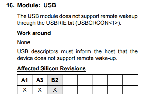
Great. Another win for Microchip. The next value, bMaxPower sets how many milliamps the device is allowed to draw, maximum, from the USB port, but divided by 2. As my device uses up to 100mA, I set this value to 0x32, which is 50 (50 x 2 = 100mA). As you can see, the maximum device a USB port can thus provide is 255 x 2 = 510mA (but the spec limits this to 500mA).
I've added comments to part of this but honestly, there's not much you can tweak and change here without breaking it, besides stuff relating to strings and endpoints.
Let's take a look at something else you may want to send to the host, namely the strings defining your device:
#define STR_DESC(l) (((((l))<<1) & 0xFF) | 0x0300)
// String descriptors. All have a common format: [byte] string_length, [byte] data_type (3 = string), UTF-16 encoded string, hence all the 0's between each 8-byte character

// Language description
unsigned char string0[] =  { 4, 0x03, 0x09, 0x04}; // 0x0409 = English

// Vendor description
unsigned short string1[] = { STR_DESC(11),
                            'A','i','d','a','n',' ','M','o','c','k','e'};

// Product description
unsigned short string2[] = { STR_DESC(12),
                            'U','S','B',' ','C','D','C',' ','T','e','s','t'};

// Serial number description
unsigned short string3[] = { STR_DESC(7),
                            '1','2','3','-','3','2','1'};

// Configuration description
unsigned short string4[] = { STR_DESC(8),
                            'U','L','T','R','A',' ','S','E'};
// Interface description
unsigned short string5[] = { STR_DESC(7),
                            'C','D','C',' ','A','C','M'};
Hmmm... OK so that may not be quite what you were expecting. All the strings are encoded in UTF-16, meaning each character takes up two bytes. The first byte is the string length (so a max of 255 again) followed by descriptor type 0x3 for string. I've combined this using a macro found on The Thirteenth Floor:
#define STR_DESC(l) (((((l))<<1) & 0xFF) | 0x0300)
So basically, if you say STR_DESC(0x8) it'll spit out 0x310.
OK! So that's how you send the configuration descriptor. There's not much left but that's enough for this time I think.
Next time I'll finish off the CDC example. Take care!