Initialising the USB peripheral post
Initialising the USB peripheral and what registers actually matter
Updated 2020-12-04 with some stuff I wasn't sure of yesterday.
Welcome to another torturously long post. This one is only for people who want to get a very basic understanding of USB in general and how to initialise the USB peripheral and some endpoints.
OK so you want to use the PIC32MZ USB peripheral. Good call! It is high speed (not full speed or low speed like most STM32 chips that need an external high speed PHY connected to them) and actually does most of the work of getting USB to work for you. It's a genuinely good peripheral in my opinion. However, USB itself is a tricky thing to get into and understand. Today I want to cover the very, very basics of how to get the USB peripheral working and how to get your first packet from the computer.
How to set up the USB peripheral and put it into High Speed mode
First off, the good old USB naming conventions w.r.t. speed need to be cleared up:
- Low Speed (LS) - 1.5 Megabits/s = 187.5kB/s max (awfully slow)
- Full Speed (FS) - 12 Megabits/s = 1.5MB/s max (fine for HID devices, etc)
- High Speed (HS) - 480 Megabits/s = 60MB/s max (what I want for my MSD [Mass Storage Device] application)
- SuperSpeed (SS) - 5 Gigabits/s = 625MB/s max (this is USB 3, not available on any PIC device I know of)
The PIC32MZ series supports High Speed, whereas the older PIC32MX series only supported up to Full Speed. So naturally, as a PIC32MZ user I'm going to be focusing purely on High Speed operation. I am also going to be focusing on making a USB device for now (i.e. a device controlled by a host like a computer). At some point I will go into USB host mode (like reading from and writing to USB flash drives) but that's a story for another time.
If you just take any old PIC32MZ board and plug it into the computer via a USB cable, nothing will happen because the USB peripheral is off by default. To get it to start communicating with the computer we need to enable it, like this:
void USB_init(void *receive_callback)
{
    USB_RECEIVE_CALLBACK = receive_callback;

    USBCSR0bits.SOFTCONN = 0;   // Initially disable it while we go into setup

    USB_address = 0;            // We haven't been given an address yet
    USBCSR0bits.FUNC = 0;       // Initially set the USB address to 0 until later when the host assigns us an address

    USBCSR2bits.RESETIE = 1;    // Enable the reset interrupt
    IEC4bits.USBIE = 1;         // Enable the USB interrupt
    USBCRCONbits.USBIE = 1;     // Enable USB module interrupt
    IFS4bits.USBIF = 0;         // Clear the USB interrupt flag.
    IPC33bits.USBIP = 7;        // USB Interrupt Priority 7
    IPC33bits.USBIS = 1;        // USB Interrupt Sub-Priority 1

    USBCSR0bits.HSEN = 1;       // Enable High Speed (480Mbps) USB mode
}
Line by line, as with all peripherals we turn the USB peripheral off while we configure it. This is controlled by the SOFTCONN bit field.
Secondly, initialise the USB address as 0. This I store both in an internal variable called USB_address and also in the hardware bit field USBCSR2.FUNC. Later on the computer will give us an address. Again, we are making a USB device, something that is controlled by a host. In this case, we can't assign ourselves an address. The host device, usually a computer, can have up to 127 USB devices attached to it and will handle assigning each of them an address by itself. More on this later.
Next, we set up the USB interrupt-related stuff. The USB peripheral communicates your our program via interrupts, and anything that happens will come into one giant interrupt handler. For now, I've set it to interrupt priority 7, sub-priority 1 but these numbers don't really matter. I've also enabled the USB interrupts in IEC4 and set the USB peripheral to generate interrupts as well as told it to generate an interrupt when a "USB reset" happens. More on this too, in a bit :)
Finally, turn on High Speed mode by setting USBCSR0bits.HSEN to 1. Setting it to 0 means we are going to be in low speed mode.
You may have notice that we didn't turn the USB peripheral on again. That's because after we've initialised it, we're supposed to wait until the VBUS pin is high, meaning we're connected to USB. If you're making a board, connect the VBUS pin on the PIC32MZ to the USB connector's VBUS pin (it's 5V tolerant so no worries there). In the project I uploaded yesterday, I didn't bother to check if we're connected, I assumed we were connected and powered by USB so if it didn't work that may be why.
OK, that's not actually too bad right? Pretty simple for a PIC32MZ peripheral really. Let's turn the USB peripheral on and get to the real fun.
void USB_connect()
{
    USBCSR0bits.SOFTCONN = 1;
}
From this moment on, the PIC32MZ and the computer will start communicating. From what I can see, the first thing the computer will do is send a "Reset" instruction to the device and it is at this point that you actually set up your device and get ready to roll. Inside your ISR (interrupt service routine), that'll look like this:
void __attribute__((vector(_USB_VECTOR), interrupt(ipl7srs), nomips16)) USB_handler()
{
    if(USBCSR2bits.RESETIF)
    {
        // So when this is set, the USB bus has been reset and we actually need to set up all the USB endpoints now

        USB_init_endpoints();

        USBCSR2bits.RESETIF = 0;

    }
}
(Side note: PLEASE make sure you add SRS (not SOFT) after the ipl (interrrupt priority level) in your ISR declarations. AUTO works as well, usually, but set it to SRS to be sure. Setting it to SOFT means the PIC32MZ has to save the registers each time the ISR is called and it wastes tons of time. Do be aware you need to set the PRISS register for this to work, which I covered in an earlier post, but setting PRISS = 0x76543210 works in a pinch).
OK, so when a reset is called for, USBCSR2bits.RESETIF is set, so we catch it and then we actually set up our endpoints. But what are endpoints?
USB Endpoints
When getting into USB on the PIC32MZ, half of the battle was trying to understand what I was reading on websites. Terms like "endpoint" and "setup packet" were thrown around and it was pretty hard to understand. Perhaps I'm just not bright enough :) Let's look at the Microchip Developer site for an image
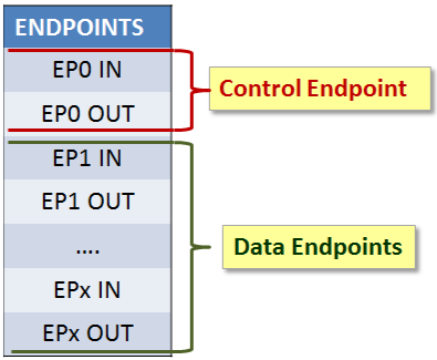
Long story short, endpoints are communications channels between your device and the host (computer or whatever that may be). An endpoint that sends data from the Host to the Device is called an OUT Endpoint. One that reads in data to the host from the device is called an IN Endpoint. This IN/OUT stuff is a bit confusing at first, but you always need to think of it from the point of view of the host, not from your PIC32MZ device. Furthermore, for High Speed and under, these endpoints are one way only (i.e. not full duplex but half duplex), though their direction can be controlled in software. So, for example, if you wanted to read a message from the host, you'd have to set your endpoint to be an OUT endpoint and then read the data. If you then wanted to send a reply, you'd have to set your endpoint to be an IN endpoint and then send the message.
There are 7 endpoints available on the PIC32MZ for us to use as we wish, numbered 1 to 7. Initially, when the device connects to the computer all communication will be done on Endpoint 0 because the computer doesn't yet known which endpoints we've chosen to use. Endpoint 0 is special and is used for what they call Control Transfers. It sends instructions from the host to the device and replies back from the device to the host.
So what happens when we plug our device in is that the host asks our device what type of device it is, what endpoints it uses and a whole bunch of other stuff. This is actually fairly involved and I won't cover it today. What I will end on today is the setup of our chosen endpoints.
Additionally, each endpoint has a mode it operates in. The valid modes are:
- Control transfers
- Interrupt transfers
- Isochronous transfers
- Bulk transfers
OK. Let's type some more! To put it fairly (perhaps too) simply:
- Control transfers are used to send messages back and forth between the host and device about the setup/configuration/status of the device.
- Interrupt transfers - Intended for small, infrequents bursts of data. In this mode the host is periodically checking to see if an interrupt has been raised so it guarantees delivery of data within a certain set time period.
- Isochronous transfers - Used for time-dependent information like audio and video. It is periodic like an Interrupt transfer but it is also continuous. However, due to the need to guarantee of time and speed of transfer, it does not retry to send on error.
- Bulk transfers - Used to transfer large blocks of non-time-dependent data in bursts. Guarantees delivery of data but not there are no time guarantees. Can use all currently available bandwidth to send data as fast as possible.
For a better explanation, please see this site.
Setting up our chosen endpoints
For the next few posts, I'm going to be covering how to write a program that'll give us a Communications Device Class (aka CDC) device. Looking at the spec for a CDC device, we see we need:
- One interrupt IN endpoint for notifications to the USB Host
- One bulk IN and one bulk OUT endpoint for data transfer
As we need two different kinds of endpoints, we need at least two endpoints. We could use three in total but I'm going to just use two. Why? Well, for a Virtual COM port it's highly unlikely we'll be looking at simultaneous two-way communication and I also want to cover how to change the endpoint modes from IN to OUT and back again :)
OK, so to carry on from the code earlier, a USB interrupt has been raised and USBCSR2bits.RESETIF was set, meaning we now need to actually do our endpoint setup. This mostly likely didn't need to be done earlier but I really struggled getting USB to work initially and it led to me being paranoid and putting it into the USB_init() function to. Anyway, onto the code:
void USB_init_endpoints()
{
    USBE1CSR0bits.MODE = 0;     // EP1 is OUT (OUT from host = in to device = RX)
    USBE2CSR0bits.MODE = 0;     // EP2 is OUT (for now, will be IN at times)

    // Clear all interrupt flags
    USBCSR0bits.EP0IF = 0;
    USBCSR0bits.EP1TXIF = 0;
    USBCSR0bits.EP2TXIF = 0;
    USBCSR1bits.EP1RXIF = 0;
    USBCSR1bits.EP2RXIF = 0;

    // Set the maximum transfer length for each endpoint
    // Configure endpoint 0 first.
    USBE0CSR0bits.TXMAXP = 16; // Set endpoint 0 buffer size to 16 bytes (can be a maximum of 64 for EP0)

    // And next my custom endpoints
    USBE1CSR0bits.TXMAXP = 16;   // Endpoint 1 - Maximum TX payload / transaction (can be a maximum of 64 for CDC "Interrupt IN endpoint"
    USBE2CSR0bits.TXMAXP = 512;   // Endpoint 2 - Maximum TX payload / transaction (512 is the maximum, set to 512)
    USBE2CSR1bits.RXMAXP = 512;   // Endpoint 2 - Maximum RX payload / transaction (512 is the maximum, set to 512)

    // Specify which kinds of endpoint we will be using
    USBE1CSR2bits.PROTOCOL = 3; // Endpoint 1 - Interrupt mode
    USBE2CSR2bits.PROTOCOL = 2; // Endpoint 2 TX - Bulk mode
    USBE2CSR3bits.PROTOCOL = 2; // Endpoint 2 RX - Bulk mode

    // Enable DISNYET
    USBE1CSR1bits.PIDERR = 0; // Clear DISNYET to enable NYET replies
    USBE2CSR1bits.PIDERR = 0; // Clear DISNYET to enable NYET replies

    // Set up buffer location for endpoint 1
    USBCSR3bits.ENDPOINT = 1;
    USBFIFOA = 0x08;
    USBIENCSR0bits.CLRDT = 1;

    // Set up buffer locations for endpoint 2
    USBCSR3bits.ENDPOINT = 2;
    USBFIFOA = 0x000A004A;
    USBIENCSR0bits.CLRDT = 1;
    USBE2CSR3bits.TXFIFOSZ = 0x9;   // Transmit FIFO Size bits - 512 bytes
    USBE2CSR3bits.RXFIFOSZ = 0x9;   // Receive FIFO Size bits - 512 bytes

    // Set maximum size for each packet before splitting occurs
    USBOTGbits.RXFIFOSZ = 0b0110; // 0b0110 = 512 bytes
    USBOTGbits.TXFIFOSZ = 0b0110; // 0b0110 = 512 bytes

    // Set receive endpoint 2 to High Speed
    USBE2CSR3bits.SPEED = 1;

    // Disable Isochronous mode for endpoints 1 and 2
    USBE1CSR0bits.ISO = 0;      // Isochronous TX Endpoint Disable bit (Device mode).
    USBE2CSR0bits.ISO = 0;      // Isochronous TX Endpoint Disable bit (Device mode).

    // Set up endpoint interrupts
    // Initially clear all the interrupt enables (IE)
    USBCSR1 = 0;
    USBCSR2 = 0;

    USBCSR1bits.EP0IE = 1;      // Endpoint 0 interrupt enable
    USBCSR1bits.EP1TXIE = 1;    // Endpoint 1 TX interrupt enable
    USBCSR2bits.EP1RXIE = 1;    // Endpoint 1 RX interrupt enable
    USBCSR1bits.EP2TXIE = 1;    // Endpoint 2 TX interrupt enable
    USBCSR2bits.EP2RXIE = 1;    // Endpoint 2 RX interrupt enable
    USBCSR2bits.RESETIE = 1;
    USBCSR2bits.RESUMEIE = 1;
    USBCSR2bits.SOFIE = 1;

    // Set current endpoint to EP2
    USBCSR3bits.ENDPOINT = 2;
}
OK that's incredibly involved. Let's take a brief overview of what we've done.
USBE1CSR0bits.MODE = 0;     // EP1 is OUT (OUT from host = in to device = RX)
USBE2CSR0bits.MODE = 0;     // EP2 is OUT (for now, will be IN at times)
Not much to see here. Just setting the current operation mode of the EPs to be OUT (receive from host). This is entirely unnecessary in this function, we only need to set them when we get an interrupt, but I'm covering here how to change the mode.
// Clear all interrupt flags
USBCSR0bits.EP0IF = 0;
USBCSR0bits.EP1TXIF = 0;
USBCSR0bits.EP2TXIF = 0;
USBCSR1bits.EP1RXIF = 0;
USBCSR1bits.EP2RXIF = 0;
Self-explanatory, clear all the flags.
// Set the maximum transfer length for each endpoint
// Configure endpoint 0 first.
USBE0CSR0bits.TXMAXP = 16; // Set endpoint 0 buffer size to 16 bytes (can be a maximum of 64 for EP0)

// And next my custom endpoints
USBE1CSR0bits.TXMAXP = 16;   // Endpoint 1 - Maximum TX payload / transaction (can be a maximum of 64 for CDC "Interrupt IN endpoint"
USBE2CSR0bits.TXMAXP = 512;   // Endpoint 2 - Maximum TX payload / transaction (512 is the maximum, set to 512)
USBE2CSR1bits.RXMAXP = 512;   // Endpoint 2 - Maximum RX payload / transaction (512 is the maximum, set to 512)
OK, here we are getting to something more interesting. This is how many bytes can be sent in a single transaction between the host and the device.
// Specify which kinds of endpoint we will be using
USBE1CSR2bits.PROTOCOL = 3; // Endpoint 1 - Interrupt mode
USBE2CSR2bits.PROTOCOL = 2; // Endpoint 2 TX - Bulk mode
USBE2CSR3bits.PROTOCOL = 2; // Endpoint 2 RX - Bulk mode
The protocol/transfer type of each endpoint needs to be set up. As discussed earlier, we need one interrupt, one bulk IN and one bulk OUT endpoint.
BE WARNED
For setting the transfer type of IN endpoints (from device to host), you change bits in USBEnCSR2 (where n = endpoint number, in my case 2), but for OUT endpoints (from host to device) you change bits in USBEnCSR3!
A further hilarious note is that in the datasheet it's called USBIEnCSR2 not USBEnCSR2. They point to the same register but XC.h seems to name them differently from the datasheet for whatever reason. I guess because they want you to use Harmony and that means you'll never need to know it? Who knows.
// Enable DISNYET
USBE1CSR1bits.PIDERR = 0; // Clear DISNYET to enable NYET replies
USBE2CSR1bits.PIDERR = 0; // Clear DISNYET to enable NYET replies
PIDERR? DISNYET? In USB host mode, this bit field is called PIDERR and in device mode it's called DISNYET (Disable NYET). It's the same field that fills two roles. The NYET (not Russian but short for No response YET) is a special kind of handshake that the device uses to tell the host that the device isn't ready for the next part of the transfer to happen. This can happen if the FIFO buffer is full or for any numbers of reasons. I now set it to 0 to enable the NYET packets.
// Set up buffer location for endpoint 1
USBCSR3bits.ENDPOINT = 1;
USBFIFOA = 0x08;
USBIENCSR0bits.CLRDT = 1;

// Set up buffer locations for endpoint 2
USBCSR3bits.ENDPOINT = 2;
USBFIFOA = 0x000A004A;
USBIENCSR0bits.CLRDT = 1;
USBE2CSR3bits.TXFIFOSZ = 0x9;   // Transmit FIFO Size bits - 512 bytes
USBE2CSR3bits.RXFIFOSZ = 0x9;   // Receive FIFO Size bits - 512 bytes
OK, we're getting to some of the real involved stuff now. Notice that we've set USBCSR3bits.ENDPOINT = 1;? That's because for some registers, like USBFIFOA, any value you put into them or read from them is valid only for the value of USBCSR3bits.ENDPOINT. So if you change ENDPOINT to 2, you'll get/set endpoint 2's information. Something to be wary of for sure!
Set the FIFO address to... 8? Not actually, no. The 8 there means 64. Due to the way the PIC32MZ's USB FIFO buffer works, the actual starting address is whatever you put in there times 8. So, in other words, start endpoint 1 TX FIFO buffer at address 64.
USBIENCSR0bits.CLRDT = 1;
According to the datasheet this "Resets the endpoint data toggle to 0". Upon further research, I've found that USB packets use DATA0 and DATA1 PIDs (Packet Identifiers) (and USB High Speed adds DATA2). In low speed and full speed transactions, when transmitting packets they toggle DATA0 and DATA1 as a form of simple error checking to know if the packet they're receiving is the one they're supposed to receive. For example, if a device receives two packets in a row with a PID of DATA0 it'll know something went wrong. DATA2 (and another one called MDATA) seems to have been added to High Speed for use with isochronous transfers and are thus beyond what I'll cover today. Thankfully this is all handled for us by the PIC32MZ's USB peripheral so we never have to worry about it.
Please see this site for more details.
USBFIFOA = 0x000A004A;
OK that looks different to endpoint 1. The first four digits are for the receive buffer's start address, which is 000A = 10 * 8 = 80. 80 because we started endpoint 1 at 64 and it's 16 bytes long, so 16 + 64 = 80. The next four digits are the transfer buffer start point. 4A, which is 74. 74 * 8 = 592 and 592 - 80 is 512, which is the length of the EP2 receive buffer. So start EP2's transfer buffer at position 592.
USBIENCSR0bits.CLRDT = 1;
USBE2CSR3bits.TXFIFOSZ = 0x9;   // Transmit FIFO Size bits - 512 bytes
USBE2CSR3bits.RXFIFOSZ = 0x9;   // Receive FIFO Size bits - 512 bytes
TXFIFOSZ and RXFIFOSZ come from the datasheet. They look like this:
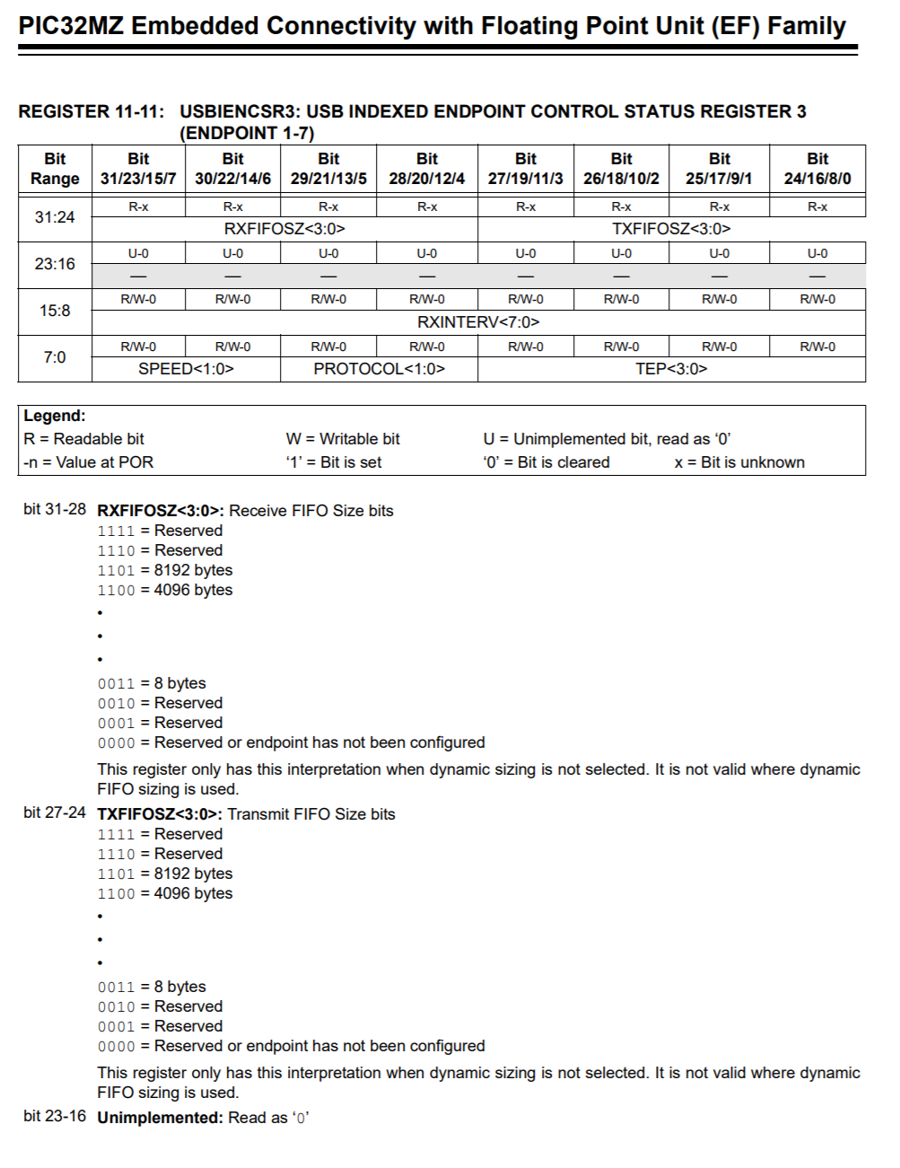
Very, very annoying how they only show some values while saving minimal space. If you work down, you'll see that 0x9 (0b1001) works out to 512 bytes maximum send and receive buffer size.
// Set maximum size for each packet before splitting occurs
USBOTGbits.RXFIFOSZ = 0b0110; // 0b0110 = 512 bytes
USBOTGbits.TXFIFOSZ = 0b0110; // 0b0110 = 512 bytes
Missing out these two lines caused my program to not work at all for a few days. If I sent more than, iirc, 8 characters to my code it'd crash the windows app and cause me much grief. Here we have a different table to work from, and 0110 means 512 bytes.
// Set up endpoint interrupts
// Initially clear all the interrupt enables (IE)
USBCSR1 = 0;
USBCSR2 = 0;

USBCSR1bits.EP0IE = 1;      // Endpoint 0 interrupt enable
USBCSR1bits.EP1TXIE = 1;    // Endpoint 1 TX interrupt enable
USBCSR2bits.EP1RXIE = 1;    // Endpoint 1 RX interrupt enable
USBCSR1bits.EP2TXIE = 1;    // Endpoint 2 TX interrupt enable
USBCSR2bits.EP2RXIE = 1;    // Endpoint 2 RX interrupt enable
USBCSR2bits.RESETIE = 1;
USBCSR2bits.RESUMEIE = 1;
USBCSR2bits.SOFIE = 1;

// Set current endpoint to EP2
USBCSR3bits.ENDPOINT = 2;
Not much to explain here. Just setting interrupt enables so that when these interrupts occurs I get notified of them in my ISR.
Phew, what an incredibly long post. Next time, CDC.
Categories: pic32