SQI on the PIC32MZ post
Refresher on SPI
A while back, I covered using the Serial Peripheral Interface (SPI) and how it worked. If you recall, we had four signals:
- Chip Select (aka Slave Select) - To choose which slave we are talking to
- Clock - Generated by the master and provided to all the slaves
- Master Out Slave In (MOSI) - For the master to send data to the slave, and
- Master In Slave Out (MISO) - For the slave to send data back to the master
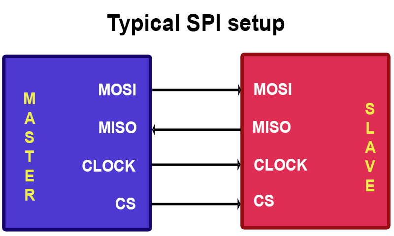
The communication was full-duplex, meaning data could be sent and received at the same time. However, the transactions had to be quite carefully controlled. If, for example, we wanted to send the command 0x9F to the slave and get a byte of data back, we'd have to do this:
<TL;DR>
As can hopefully be seen in the thrilling animation above, the master starts off sending a the byte 0x9F to the slave. At the same time, the slave is also sending data to the master. Until the slave has received the whole 8 bits, it does not know what the master is sending to it. So it has to wait until it receives the 8 bits, formulate a response and then send it out to the master the next time. Assuming it generates the response instantly, it still has no way to send the data back to the master because only the master can generate clock signals. This is why the master is seen to again be sending 0xFF (a dummy value) to the slave, purely to provide it with the clock signals it needs to send the data back to the master. 0xFF is typically used to avoid confusion with actual commands.
</TL;DR>
If we look at the code, we'd have to do this:
// Send the 0x9F byte
SPI1BUF = 0x9F;
// Wait until the reply has been received
while (SPI1STATbits.SPIRBE);
// Very important: read the reply from the buffer to clear the buffer
reply = SPI1BUF;
// Now we need to read the reply
// Send a dummy byte 0xFF
SPI1BUF = 0xFF;
// Wait until the reply has been received
while (SPI1STATbits.SPIRBE);
// Read the actual reply we want
reply = SPI1BUF;
So as you can see, it's fairly involved and there's a lot of hand-holding required. The speed is also not fantastic. We have a maximum speed of 50MHz, though some peripherals only work up to 20Mhz or even less. We can also send only one bit at a time, so even at 50MHz, we're only getting a maximum transfer rate of 6.25MB/s. This is where Serial Quad Interface (SQI) comes in.
So what is SQI?
SQI, as the name implies, can transfer up to 4 bits at once. While SPI uses 4 lines, SQI uses 6. They are:
- Clock - The same as SPI, generated by the master
- Chip select - Again, the same as SPI
- D0 - The first data bit
- D1 - The second data bit
- D2 - The third data bit
- D3 - The fourth data bit
<TL;DR>
"Up to"? Yes, SQI can be configured to send either 1 bit, 2 bits or 4 bits at a time. Many external devices that support both SPI and SQI start up in SPI mode and need to be sent a special command in order to switch to SQI mode. The PIC32MZ SQI peripheral fully supports this, thankfully, so if you really wanted you could use the SQI peripheral as a regular SPI peripheral.
</TL;DR>
From this, we can see the major difference between SPI and SQI. With SPI, we had one line for sending data to the slave and one line for receiving data and they were both in use at the same time. That is to say that communication was full duplex. With SQI, communication can only occur in one direction at a time, it is half duplex.
Let's take a look at a typical SQI connection:
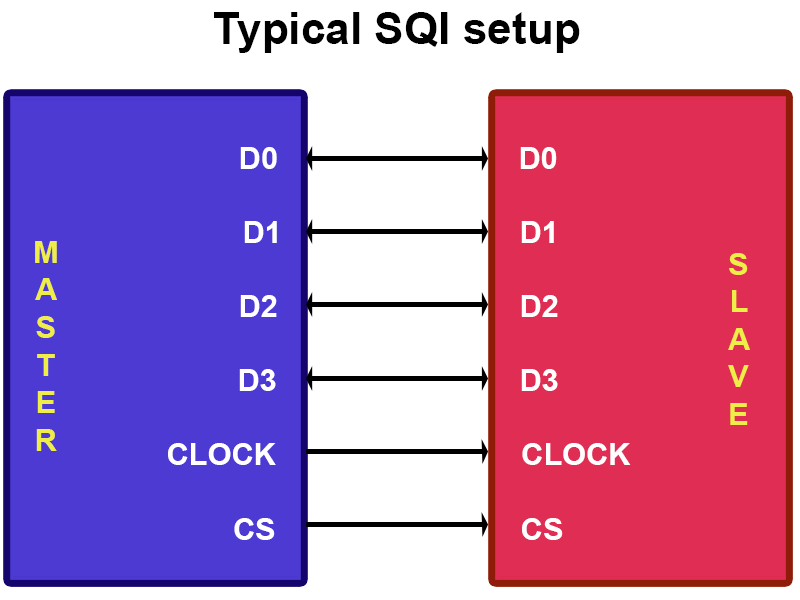
OK, not that hard so far. The hard part comes next.
The PIC32MZ's SQI peripheral
One of the most important things to remember with SQI on the PIC32MZ is that the communication can only happen in one direction at a time. This means we need some way of telling the PIC32MZ whether we want to send or receive data. This also means that, unlike the SPI peripheral, we cannot just write data to the SQI buffer and hope it'll get sent because it won't.
It turns out there are six registers we need to concern ourselves with:
- SQI1THR - SQI Threshhold Control Register
- SQI1INTTHR - SQI Interrupt Threshold Register
- SQI1CMDTHR - SQI Command Threshhold Register
- SQI1CON - SQI Control Register
- SQI1TXDATA - SQI Transfer Data Buffer Register
- SQI1RXDATA - SQI Receive Data Buffer Register
OK, that's a lot of registers, but why? Well, with SQI Microchip decided you know what, why don't we make this as fancy as we can? And to their credit, it is very fancy, but it can be very confusing too. Whereas with SPI we had to handle the transactions one by one, that is no longer the case with the SQI peripheral. Everything now works with buffers, meaning I can load up a whole list of transactions and it'll do them one by one. I repeat, writing to any of these registers will add whatever you've written to a buffer (or a queue).
This means that for every transaction with SQI, I need to tell it how many bytes I want to send or receive, how many lanes (1, 2 or 4) I will use and whether or not it's a send or receive transaction and then write the data to SQI1TXDATA (or read it from SQI1RXDATA). It can be confusing, so I'll go into it more in a moment.
If you've been following along with the PIC32MZ datasheet, you may have experienced cases where the datasheet contradicts itself multiple times. The SQI is one such case and why it's taken so long for me to get this code working at an acceptable level! As such, some of these registers remain a bit of a mystery to me but I know they have to be set in order for stuff to work :) Let's take a look at them one by one, very briefly.
SQI1THR
I think this controls how many transactions we can queue up in the SQI Control buffer. I just set it to 0x100 when I initialise the SQI peripheral and never touch it again.
SQI1INTTHR
I think this is used to set how many bytes transferred or received will trigger a transfer or receive interrupt. Again, I just set it to 0x100 when I initialise the SQI peripheral and never touch it again.
SQI1CMDTHR
I think this is used to set how many bytes need to be in the send or receive buffer before the SQI periperhal will start doing anything. I again set this before each transaction and I set it to be the same as the number of bytes I'm about to transmit/receive. The lower 6 bits are receive bytes and bits 8 to 13 are for transmit bytes.
SQI1CON
Finally, one I understand. This is used to tell the SQI peripheral how many bytes we are going to write to SQI1TXDATA (or read from SQI1RXDATA), how many lanes (so 1-lane (like SPI), 2-lane or 4-lane) and what kind of transaction it is, be it send or receive. There are other things it can do but I'm limiting it to this much today. It bears looking at how it's defined in the datasheet:
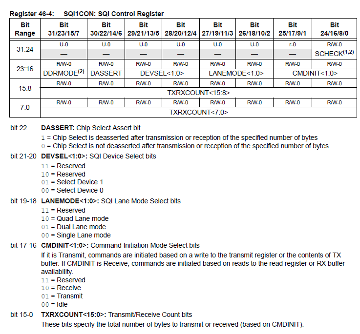
Note: There are two Chip Select pins (SQICS0 and SQICS1) so I presume that's where device 0 and 1 come from. I don't use either, I use a different pin as chip select and have only been able to get it to work using device 1. No, I don't know why.
Note 2: TXRXCOUNT is an ambitious 16 bits wide but the actual buffer itself is much smaller at 32 bytes, so this number should never exceed 32.
SQ1ITXDATA
Writing to this register will cause whatever data we write to be pushed into the transmit buffer. Note, however, that it defaults to writing 32-bits of data to the SQI transmit buffer!. This means that this:
unsigned char tmp = 128;
SQI1TXDATA = tmp
Will actually write 4 bytes of data to the transmit buffer (that is, 0x00 0x00 0x00 0x80)! If you want to write only 8 bits, you need to perform this trick:
unsigned char *TXDATA = (unsigned char *)&SQI1TXDATA;   // Address to write to for 8-bit data
*TXDATA = 128;
This is unlike SPI and is something to be wary of!
SQI1RXDATA
Reading from this register will pop whatever is on the top of the receive buffer off. Like with SQI1TXDATA, to access an 8-bit value, you have to do the following:
unsigned char *RXDATA = (unsigned char *)&SQI1RXDATA;   // Address to read from for 8-bit data
unsigned char result;
result = *RXDATA;
OK, so how do we use this in code?
First up, we have to initialise the SQI peripheral. Bear in mind it is connected to Reference Clock 2, so that is some we first have to set up. The initialisation is done like this:
void SQI_init()
{
    CFGCONbits.TROEN = 0; // Disable trace outputs because SQI share them

    // Set up Reference Clock 2
    if (!REFO2CONbits.ACTIVE)
    {
        REFO2CONbits.RODIV = 1;
        REFO2CONbits.ROSEL = 1;
        REFO2CONbits.ON = 1;
        while (REFO2CONbits.DIVSWEN);
        REFO2CONbits.OE = 1;
    }

    // Turn *off* clock division according to the errata
    SQI1CLKCONbits.CLKDIV = 0;
    SQI1CLKCONbits.EN = 1;
    // Wait until the SQI clock reports it is stable
    while (!SQI1CLKCONbits.STABLE);

   // Tell the SQI peripheral to reset
    SQI1CFGbits.RESET = 1;
    SQI1CFGbits.CPOL = 0;
    SQI1CFGbits.CPHA = 0;
    // Set the mode to 1, which is PIO mode (where we control it directly)
    SQI1CFGbits.MODE = 1;
    // Enable burst mode, again as datasheet says
    SQI1CFGbits.BURSTEN = 1;
    // Enable the SQI peripheral
    SQI1CFGbits.SQIEN = 1;
    // Enable data lines SQID0, SQID1, SQID2 and SQID3
    SQI1CFGbits.DATAEN = 0b10;

    // Set up buffers to trigger as soon as 1 byte is present
    SQI1THR = 0x100;
    SQI1INTTHR = 0x100;
}
OK, now it's set up, how on earth do we use the thing?
My first example today is very basic. I am communicating with an 8MB PSRAM. The PSRAM starts up in SPI mode. So initially, what I want to do is send it the command 0x9F, which will cause it to send me it's EID information. Again, this is what I want to do:
- Send the 8-bit command 0x9F
- Send 3 dummy bytes for address (as the PSRAM datasheet says to)
- Read 8 bytes of data as a response
In code, I'd do this:
void SRAM_get_EID(unsigned int *buf)
{
    // Pull CS low, select the PSRAM
    SRAM_select(0);

    // Set up for 4 bytes initially
    SQI1THR = 0x100;
    SQI1INTTHR = 0x100;

    // Sending 4 bytes, 0x9F "Get EID" command and 3 empty address bytes
    SQI1CMDTHR = 0x100;
    // Deassert chip select when done, using device 1, using single lane mode, transmit command, 4 bytes
    SQI1CON = 0x00510004;
    // Remember, this next line actually sends 0x00 0x00 0x00 0x9F!
    SQI1TXDATA = 0x9F;

    // Wait until the transmit buffer is empty i.e. the data has been fully transmitted
    while (SQI1STAT1bits.TXBUFFREE < 32);

    // Trigger on each byte received
    SQI1CMDTHR = 0x01; // Receive 8 bytes
    // Deassert chip select when done, using device 1, using single lane mode, receive command, 8 bytes
    SQI1CON = 0x00520008;

    // Wait until the lower 8 bits of SQI1STAT1 (which are received bytes count) = 8
    while ((SQI1STAT1 & 0xFF) != 0x08);

    // Read the first 4 bytes and store them in the array pointer
    *buf = SQI1RXDATA;
    // Move array pointer to next element
    buf++;
    // Read the final 4 bytes and store them in the array pointer
    *buf = SQI1RXDATA;

    // Set CS high again, deselect the PSRAM
    SRAM_select(1);
}
This same PSRAM then has a command to set it into quad lane mode (command 0x35, but this time with no dummy bytes). I'd do this as follows:
void SRAM_go_SQI()
{
    // We want to write an 8-bit value to the SQI transmit buffer, so set that up
    unsigned char *TXDATA;
    TXDATA = (unsigned char *)&SQI1TXDATA;

    // Pull CS low, select the PSRAM
    SRAM_select(0);

    SQI1THR = 0x100;
    SQI1INTTHR = 0x100;
    // Trigger on 4 bytes, though this works just fine
    SQI1CMDTHR = 0x100;
    // Deassert chip select when done, using device 1, using single lane mode, transmit command, 1 byte
    SQI1CON = 0x00510001;

    // Write the 8-bit value 0x35 to the transmit buffer
    *TXDATA = 0x35;

    // Wait until the transmit buffer is empty i.e. the data has been fully transmitted
    while (SQI1STAT1bits.TXBUFFREE < 32);

    // Set CS high again, deselect the PSRAM
    SRAM_select(1);
}
Now that we're in quad lane mode, let's try writing some data to that PSRAM. First, we need to tell the PSRAM we are going to be writing to it. The quad-lane write command is 0x38 and it needs to be followed by a 3-byte address. We'll do it like this:
void SRAM_start_write_quad(int address)
{
    // We're about to have some endian fun
    unsigned int data;
    unsigned int endian[3];

    // Pull CS low, select the PSRAM
    SRAM_select(0);

    // Trigger on 4 bytes
    SQI1CMDTHR = 0x00000400;
    // Deassert chip select when done, using device 1, using quad lane mode now, transmit command, 4 bytes
    SQI1CON = 0x00590004;

    // Now, if our address is 0x123456, we are going to have to switch that around to 0x563412 because the PIC32 is a little-endian device. Yay.
    endian[0] = address >> 16;
    endian[1] = (address & 0x00FF00) >> 8;
    endian[2] = (address & 0xFF);

    address = (endian[2] << 16) | (endian[1] << 8) |(endian[0]);
    data = (address << 8) | 0x38;

    // The actual order of bytes *sent* will be 0x38, address[16:23], address[8:15], address[0:7].
    // I've done it in a bit of a round-about way to hopefully make it clearer.

    // Send the 4 bytes of data to the transfer queue
    SQI1TXDATA = data;

    // Wait until the transmit buffer is empty i.e. the data has been fully transmitted
    while (SQI1STAT1bits.TXBUFFREE < 32);

    // NOTE: HERE I DO NOT SET THE CHIP SELECT LINE HIGH. That would indicate to the PSRAM chip that the transaction was over!
}
OK, so I've told it to get ready for data, now let's write that data in super fast quad lane mode, one byte at a time:
    for (cnt = 0; cnt < num_bytes; cnt++)
    {
        // Set SQI TX command threshold to 1 byte in a slightly different way why not
        SQI1CMDTHRbits.TXCMDTHR = 1;
        // Deassert chip select when done, using device 1, using quad lane mode now, transmit command, 1 byte
        SQI1CON = 0x00590001;

        // Send an 8-bit value to the buffer
        *TXDATA = buffer[cnt];

        // Wait until the transmit buffer is empty i.e. the data has been fully transmitted
        while (SQI1STAT1bits.TXBUFFREE < 32);
    }

    // Now I can set Chip Select high again and thus deselect the PSRAM because I'm done writing
    SRAM_select(1);
Would it be faster if I didn't send one byte at a time and then nanny over the transmit buffer? Surely it would, yes. However, as this is an intro to getting SQI to work let's keep it as safe as we can for now :)
Phew, and now we've written data to the PSRAM. In the example code below I've included code for reading and writing in both single and quad-lane mode.
Please bear in mind that on my development board the PSRAM's Chip Select is connected to Port RJ1
Here's the code. Good luck!
Categories: pic32