I2C on the PIC32MZ post
What is I2C?
I2C is short for Inter-Intergrated Circuit, and people pronounce it I-squared-C or I2C. It's a way of connecting multiple ICs using just two wires, called the Serial Data Line (SDA) and the Serial Clock Line (SCL). Before I even begin, there is something very important to be aware of. The lines are open-drain (aka open-collector). This means that devices on the I2C bus can only pull the lines low or leave them open/floating.
This means that both SDA and SCL need a pullup resistor or they will not be able to set the lines high.
To further drive this home, this is what I mean:
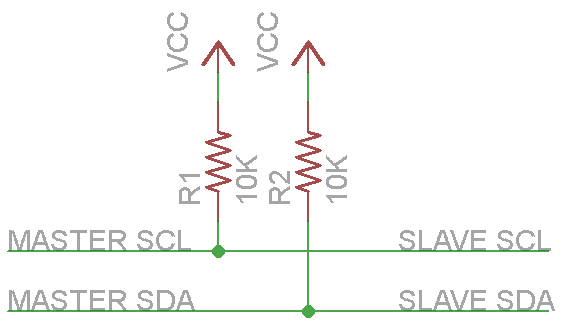
I've personally seen the value of these resistors be anywhere from 1.8k to 47k with many people recommending 4.7k or 10k. The important thing is that they are there.
I repeat, I2C will not work at all without these pullup resistors. Got it? Good, because that really wasted a lot of my time the first time I tried to use I2C. OK, on with the show.
An overview of the I2C protocol
Both SDA and SCL are bidirectional communication signals, they can be changed by either master or slave. Compare this to SPI which needed 3 (MISO, MOSI and CLK) just for communication and then an additional Chip Select for each device and you can see why this can be benficial in systems with multiple devices. Of course, using only two wires means to talk to a lot of devices means that I2C is going to be both more complex and slower than SPI but it's very useful nonetheless.
Today we are going to take a look at the most common situation us hobbyists find ourselves in, namely with one master device and with multiple slave devices. The master is responsible for initiating communication and providing the clock signals. For the purposes of today's article, the PIC32MZ is going to be the master device.
<TL;DR>
What if the clock signal is too fast for the slave device to handle, or it needs extra time to process data? In the I2C protocol there is a way for slave devices to force the master to wait and this is called clock stretching. In master mode, the PIC32 can detect and handle this automatically and we don't need to worry about it. If we want to implement clock stretching, we can do so by setting the STR_EN bit in I2CxCON.
</TL;DR>
So how does it all work? Well, all devices are connected to the same SDA and SCL wires, forming what is known as a bus. Each device on the bus has its own unique address. Slave devices are constantly listening out for this address to be broadcast.
Once a special signal called a start signal is seen on the bus, slave devices wake up and listen. The first data sent is always the address of the slave device we want to talk to. Once a slave device sees its address on the bus, it replies to the master and communication begins. The rest of the devices then ignore the following transfers. Today let's assume that everything is set up nicely and no devices have the same addresses or anything strange like that. I will also be assuming that the devices used have 7-bit addresses. I have read that I2C supports 10-bit devices but I've never seen one myself and I've been through tons of eBay and Aliexpress modules.
So when we write an I2C slave's address to the bus, how does it know whether we want to write to it or read from it? Well, assuming we're using 7-bit addresses it looks like this:

So there you can see the 7-bits of the address and two other bits. The first, labelled RW, is the Read/Write bit. This tells the device we're talking to whether we're wanting to read from it (RW set to 1) or write to it (RW set to 0). The second, labelled ACK, is the Acknowledge bit. This is used to tell the device we received data successfully from it and are ready to continue. If we do not send the ACK bit the device sending the data will assume we are not ready to receive more data.
Something to bear in mind, therefore, is that it takes 9 SCL clock pulses to send an 8-bit byte of data because the Acknowledge bit needs to be sent/received too and the master is responsible for generating that clock pulse. Also note that for data bytes there is no Read/Write bit, this is all set up initially when sending out the address. This means that if you want to write some data and then immediately read some data again you will need to send another start signal and another address byte with the read/write bit set.
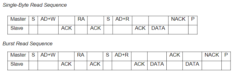
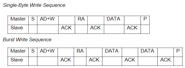
There are several kinds of signals that you need to be aware of when using I2C:
- Start - Tells the slave devices on the bus to start listening.
- Stop - Ends communication, telling slave devices they can go back into idle mode. To restart communication a new start signal must be sent.
- Acknowledge (ACK) - Used by devices receiving data to acknowledge they have received the data and are ready for more data.
- Not Acknowledge (NACK) - Not really a signal of its own, just a way to skip the acknowledge signal. This could be because either no more data is wanted or the device is not ready to receive more data.
- Write - Writes a byte to the I2C bus. For this to be a write, the Read/Write bit must be set to low.
- Read - Read a byte from the I2C bus. For this to work, the Read/Write bit must be set to high.
There is one more called the repeated start. This is used when we want to continue sending data and don't want to have to stop and start again with the same slave device.
<TL;DR>
Although the PIC32MZ hardware handles the signals electrically, let's take a look at what those signals mean in terms of setting SDA and SCL high and low. Bear in mind that, due to the pullup resistors that you did not forget about, the default values of SCL and SDA are high.
- Start - SCL remains high and SDA changes from high to low.
- Stop - SCL remains high but SDA changes from low to high.
- Repeated start - Electrically the same as start
- Acknowledge - SDA is set low while SCL sends a clock pulse
- Not acknowledge - SDA is set high while SCL sends a clock pulse
</TL;DR>
Order of operations
Let's take a look at two example. In the first, a byte (8-bits) of data is being written to a slave that has an I2C address of 0x68. The slave's internal register number is 0x56 and we want to set it to a value of 0x23.
The order of operations would be:
- Send start signal
- Write slave address with Read/Write bit set to 0 (Send 0x68 << 1 = 0xD0)
- Receive ACK
- Write register address (0x56)
- Receive ACK
- Write data value (0x23)
- Send stop signal
That second line is going to be confusing. Take a look again at how the 9-bit number is made up above. We are actually only sending 8 bits, the ACK is automatic so let's look at the first 8 bits. The upper 7 bits contain the slave's address and the least significant bit is the R/W bit. This means that 7-bit I2C addresses need to be shifted left by 1 when writing them to the I2C bus.
For the second example, 8 bits of data will be read from the same slave, register number 0x73.
The order of operations would be:
- Send start signal
- Write slave address with Read/Write bit set to 1 (Send 0x68 << 1 | 1 = 0xD1)
- Receive ACK
- Write register address (0x75)
- Receive ACK
- Receive data byte (8-bits)
- Send NACK
- Send stop signal
Again, that second line. If we want to set the least significant bit, we can either add 1 to the address or OR it by 1, which I prefer because it looks more confusing.
Also, why am I sending a NACK instead of an ACK? This is because I only want to receive one 8-bit number and end the transaction. If I send an ACK, the slave device will start sending me more data.
The PIC32MZ I2C hardware and registers
The PIC32MZ I2C hardware is generally very easy to use. There is no Peripheral Pin Select (PPS) stuff to worry about, the pins are hardwired. The 144-pin device I uses has five I2C peripherals. Today I will be looking at using the first one, namely I2C1. This means the two physical pins I will connect to are SDA1 (on port RA15) and SCL1 (on port RA14).
Although I've made I2C seem incredibly difficult, it's very easy to use on the PIC32MZ. The following registers are used:
- I2C1BRG - I2C1 Baud Rate Generator Register - Used for setting the speed of the I2C peripheral
- I2C1CON - I2C1 Control Register - Used to set up I2C
- I2C1TRN - I2C1 Transmit Data Register - Contains data we want to send onto the I2C bus
- I2C1RCV - I2C1 Receive Data Register - Contains data received from the I2C bus
- I2C1STAT - I2C1 Status Register - Contains the status of the I2C peripheral
Setting the speed of the I2C peripheral
OK, before we can jump straight into the code, let's take a look at that I2C1BRG register. It can run from 100kHz to 1Mhz, according to the product page for the PIC32MZ. I often run it at 400kHz in fact. However, as with all things PIC32MZ there are surprises contained in documents. In this case, the "PIC32MZ Embedded Connectivity with Floating Point Unit (EF) Family Silicon Errata and Data Sheet Clarification".
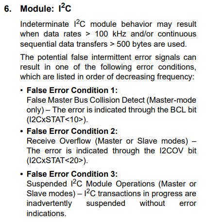
In short, Microchip thinks that "software" solutions for their terrible I2C peripheral are acceptable. By software, they mean implementing the entire I2C protocol yourself on a port you want. Thankfully, 100kHz seems to work fine on I2C1. Please note, I2C3 straight up doesn't work according to the datasheet. I repeat, I2C3 does not work at all, do not use it!
So today, we're going to run at 100kHz because nobody has the time to debug impossible to find errors later on. Here's the formula for setting I2C1BRG to 100kHz:
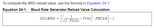
This formula is a bit harder than the SPI formula, but not too much so:
- TPGD is a propagation delay, defined in the PIC32MZ EF datasheet as 104ns.
- FSCK is the speed we want, so 100kHz for my example.
- PBCLK is the speed of the peripheral bus clock. I2C uses Peripheral Bus Clock 2 (PBCLK2), which I've set to 100MHz.
So let's take a look at the code to do that:
// I2C_init() initialises I2C1 at at frequency of [frequency]Hz
void I2C_init(double frequency)
{
    double BRG;

    I2C1CON = 0;            // Turn off I2C1 module
    I2C1CONbits.DISSLW = 1; // Disable slew rate for 100kHz

    BRG = (1 / (2 * frequency)) - 0.000000104;
    BRG *= (SYS_FREQ / 2) - 2;

    I2C1BRG = (int)BRG;     // Set baud rate
    I2C1CONbits.ON = 1;     // Turn on I2C1 module
}
For stuff like this I always use double precision floating point numbers instead of setting registers directly. This makes debugging easier when stuff doesn't work later on :)
<TL;DR>
Slew rate? For bus speeds of 400kHz, the I2C specification requires that we have slew rate (or rate of change of output) control. For 100kHz, this should be disabled by setting DISSLW to 1.
</TL;DR>
Start, stop, restart, ACK and NACK
All of these are contained in one register, I2C1CON:
- I2C1CONbits.SEN - Start Condition Enable bit
- I2C1CONbits.PEN - Stop Condition Enable bit
- I2C1CONbits.RSEN - Restart (Repeated start) Condition Enable bit
- I2C1CONbits.ACKDT - Acknowledge Data bit. Set to 0 to ACK and 1 for NACK.
- I2C1CONbits.ACKEN - Acknowledge Sequence Enable bit
There's a bunch of code here but it's fairly straightforward. I've separated them all into their own functions for readability:
// I2C_wait_for_idle() waits until the I2C peripheral is no longer doing anything
void I2C_wait_for_idle(void)
{
    while(I2C1CON & 0x1F); // Acknowledge sequence not in progress
                                // Receive sequence not in progress
                                // Stop condition not in progress
                                // Repeated Start condition not in progress
                                // Start condition not in progress
    while(I2C1STATbits.TRSTAT); // Bit = 0 ? Master transmit is not in progress
}

// I2C_start() sends a start condition
void I2C_start()
{
    I2C_wait_for_idle();
    I2C1CONbits.SEN = 1;
    while (I2C1CONbits.SEN == 1);
}

// I2C_stop() sends a stop condition
void I2C_stop()
{
    I2C_wait_for_idle();
    I2C1CONbits.PEN = 1;
}

// I2C_restart() sends a repeated start/restart condition
void I2C_restart()
{
    I2C_wait_for_idle();
    I2C1CONbits.RSEN = 1;
    while (I2C1CONbits.RSEN == 1);
}

// I2C_ack() sends an ACK condition
void I2C_ack(void)
{
    I2C_wait_for_idle();
    I2C1CONbits.ACKDT = 0; // Set hardware to send ACK bit
    I2C1CONbits.ACKEN = 1; // Send ACK bit, will be automatically cleared by hardware when sent
    while(I2C1CONbits.ACKEN); // Wait until ACKEN bit is cleared, meaning ACK bit has been sent
}

// I2C_nack() sends a NACK condition
void I2C_nack(void) // Acknowledge Data bit
{
    I2C_wait_for_idle();
    I2C1CONbits.ACKDT = 1; // Set hardware to send NACK bit
    I2C1CONbits.ACKEN = 1; // Send NACK bit, will be automatically cleared by hardware when sent
    while(I2C1CONbits.ACKEN); // Wait until ACKEN bit is cleared, meaning NACK bit has been sent
}
Writing data to the I2C bus
This is simply a matter of writing to the I2C1TRN register, waiting for the Transmit Buffer to be empty by checking Transmit Buffer Full (TBF) flag and then waiting for the slave device to Acknowledge receipt.
// address is I2C slave address, set wait_ack to 1 to wait for ACK bit or anything else to skip ACK checking
void I2C_write(unsigned char address, char wait_ack)
{
    I2C1TRN = address | 0;              // Send slave address with Read/Write bit cleared
    while (I2C1STATbits.TBF == 1);      // Wait until transmit buffer is empty
    I2C_wait_for_idle();                // Wait until I2C bus is idle
    if (wait_ack) while (I2C1STATbits.ACKSTAT == 1); // Wait until ACK is received
}
Reading data from the I2C bus
For reading, we tell the I2C module to receive data, wait for it to clear the flag and until the receive buffer is full by checking Receive Buffer Full (RBF) flag and then send either an ACK or a NACK.
// value is the value of the data we want to send, set ack_nack to 0 to send an ACK or anything else to send a NACK
void I2C_read(unsigned char *value, char ack_nack)
{
    I2C1CONbits.RCEN = 1;               // Receive enable
    while (I2C1CONbits.RCEN);           // Wait until RCEN is cleared (automatic)
    while (!I2C1STATbits.RBF);          // Wait until Receive Buffer is Full (RBF flag)
    *value = I2C1RCV;                   // Retrieve value from I2C1RCV

    if (!ack_nack)                      // Do we need to send an ACK or a NACK?
        I2C_ack();                      // Send ACK
    else
        I2C_nack();                     // Send NACK
}
Actually using all this stuff in the real world
Theory is fun and all, but let's look at an example of using this in an actual slave device. I have a MPU-9250 module (9 degrees of freedom) module. It's a very complex module and I'm not going into it deeply today. However, as a test of whether or not I2C is working it'll do. Let's look in the datasheet for the MPU-9250 to find the address:

OK good, so I connect AD0 to ground and then the address will be 0x68. Excellent. Let's see what registers I can read from to make sure I2C is working:
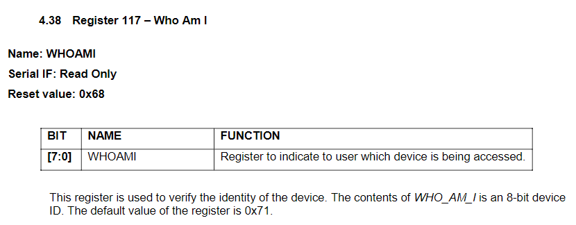
Excellent again. Register 117 (0x75) should return 0x68. Or 0x71...? Or in my case, 0x73. I think it must be a revision number or clones use something different. Point is, it's consistent and I've tested it with multiple modules to make sure it works and isn't random :) Let's see what the MPU9250's datasheet says about reading and writing:
OK, nothing too hard there. Let's see how the code for that looks:
#define MPU9250_ADDRESS 0x68            // The address of MPU9250 when the AD0 pin is connected to ground
#define MPU9250_WHOAMI  0x75            // Will return a set value based on device, in my case 0x73

// Write byte value to register at reg_address
void MPU9250_write(unsigned char reg_address, unsigned char value)
{
    I2C_start();                        /* Send start condition */
    I2C_write(MPU9250_ADDRESS << 1, 1); /* Send MPU9250's address, read/write bit not set (AD + R) */
    I2C_write(reg_address, 1);          /* Send the register address (RA) */
    I2C_write(value, 1);                /* Send the value to set it to */
    I2C_stop();                         /* Send stop condition */
}

// Read a byte from register at reg_address and return in *value
void MPU9250_read(unsigned char reg_address, unsigned char *value)
{
    I2C_start();                        /* Send start condition */
    I2C_write(MPU9250_ADDRESS << 1, 1); /* Send MPU9250's address, read/write bit not set (AD + R) */
    I2C_write(reg_address, 1);          /* Send the register address (RA) */
    I2C_restart();                      /* Send repeated start condition */
    I2C_write(MPU9250_ADDRESS << 1 | 1, 1); /* Send MPU9250's address, read/write bit set (AD + W) */
    I2C_read(value, 1);                 /* Read value from the I2C bus */
    I2C_stop();                         /* Send stop condition */
}

unsigned char main()
{
    unsigned char value;

    // Set performance to ultra rad
    set_performance_mode();

    // Moved all the ANSEL, TRIS and LAT settings to their own function
    setup_ports();

    // Enable multi-vectored interrupts mode
    INTCONbits.MVEC = 1;

    // No need to set up PPS, I2C hardware is fixed to certain pins. SCL1 = RA14, SDA1 = RA15

    // Initialise I2C1 at 100kHz
    I2C_init(100000);

    while (1)
    {
        /* Read the value at register 0x75, the MPU9250's WHOAMI register. Should return 0x68, 0x71 or 0x73 depending on version. */
        MPU9250_read(MPU9250_WHOAMI, &value);

        /* Wait 10ms before trying again so as not to overwhelm the MPU9250 or the PIC32MZ's I2C peripheral */
        delay_ms(10);
    }
}
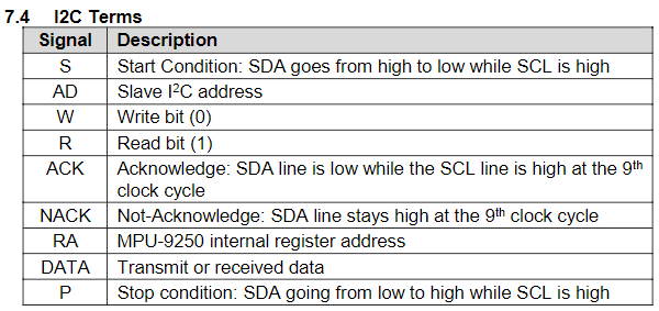
So I ran that, and here's what I got on my oscilloscope:
Cyan is SDA and magenta is SCL. Just looking at that provides no real understanding of what's happening so I created another Photoshop monsterpiece for my dear nonexistent readers. Click on it to see it in its full glory:
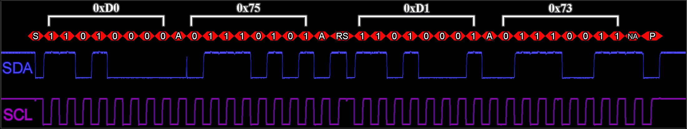
Yep, looks like the code. Phew. With that, another long-winded post is over. Good luck!
Categories: pic32