I2S and Reference Clocks on the PIC32MZ post
What is I2S?
I2S is short for Inter-IC sound, and people call it various things like I-I-S, I-squared-S, I2S etc. but what's important is that it behaves a lot like SPI, which I covered a few posts back. To think of it very basically, it is SPI plus a few other clock signals and it's used for sending audio data to chips like Digital to Analog Converters (DACs). In today's example I will be using the CS4334 DAC, a 5V DAC that I have used for some time. I'm going to modify the existing MP3 player app to use this DAC instead of PWM.
What signals does the CS4334 need from the PIC32MZ?
Let's take a look at the CS4334's datasheet:
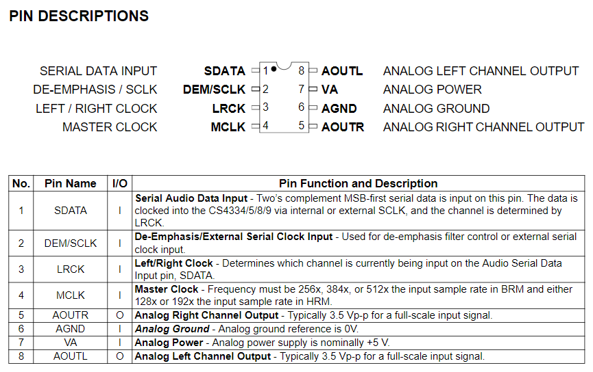
It needs SDATA, DEM/SCLK. LRCK and MCLK. Let's run over what those pins do:
- SDATA is the actual data line, in the SPI examples before it would have been SDI/SDO.
- DEM/SCLK I will use as SCLK, the SPI data clock, and not as DEM or de-emphasis clock.
- MCLK is the master clock, which I will discuss below. I will set this to 256x the SCLK frequency.
- LRCK controls whether the data being input into SDATA is for the left or right channel. It's low for left channel data and high for right channel data.
In the description for MCLK, we can see that the clock speeds needs to be 256x the sample rate of the audio. For a 44.1kHz signal, this means the MCLK clock frequency needs to be 256 x 44,100 = 11,289,600Hz.
Before we look at how to set this all up, let's go over what each of those signals requires:
- MCLK, as discussed above, needs to be 256 x 44,100Hz or 11,289,600Hz.
- SCLK needs to send 44,100 16-bit words of data per channel each second.
- LRCK needs to switch between high and low 2 x 44,100 = 88,200 times per second.
That SCLK calculation can be a bit tricky to understand. To ease our understanding of it, let's say that two 16-bit channels together gives us 32-bits of data for each "audio frame" and we need to send 44,100 audio frames per second.
LRCK only changes when we have sent some data, and it changes like this:
- It starts out low, and then we send data for the left channel.
- When the data is sent, it automatically goes high and then we send data for the right channel.
- When the data is sent, it automatically goes low again, and this repeats until we tell it not to.
Generating all those different clock signals
As I stated before, the I2S peripheral works very similarly to how the SPI peripheral does. For the purposes of this post, one of the main differences is that the Slave Select (SS) pin can be used to automatically generate the LRCK signal for us, which is great. So that takes care of that clock signal at least, but what about that massive MCLK signal? You might think you can get away with using a timer but let's see what that'd entail:
- If SYSCLK is 200Mhz then PBCLK3 is a max of 100MHz.
- We need a 11.2896MHz clock signal at 44.1kHz, or even 12.288MHz at 48kHz
- Timer period calculation gives us 100,000,000 / 11,289,600 = 8.85.
The first apparent problem is that the period needs to be a whole number, so we'll either have to round up or round down. Let's see what that gives us:
100,000,000 / 9 = 11.111MHz which we then need to divide by 256 to get our playback frequency, so 43,402Hz. Not great. Well then, how about dividing by 8?
100,000,000 / 8 = 12.5MHz / 256 = 48,828Hz. That's even worse.
Further, with a period as low as 8.85, the PIC32 is going to have to call an interrupt every 8 clock ticks and even if that's possible it's going to leave almost zero free time to run any other code. Thankfully, there's a bit of hardware that can help us and it's called the Reference Clock Output.
Using the Reference Clock Output (REFCLKO)
There are two things to know about using the Reference Clock Output as it pertains to today's post. The first is found in the datasheet under the SPIxCON register:
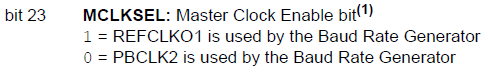
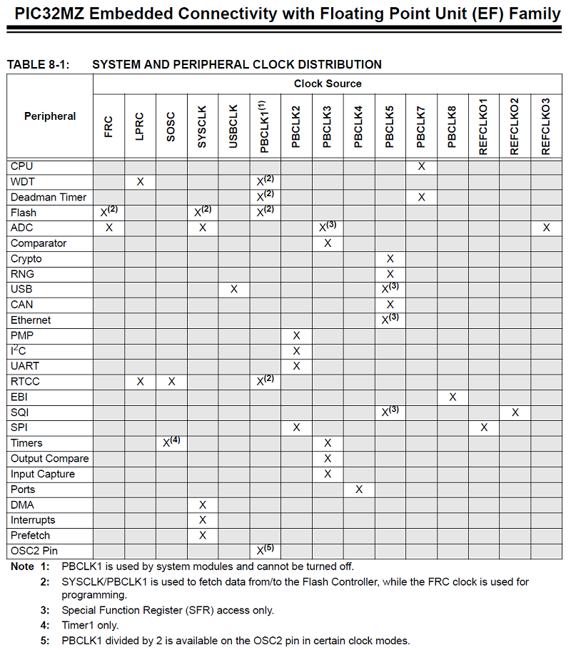
As that shows, we can only use Reference Clock 1 for SPI/I2S. This can also be found in the Clock Distribution section of the same datasheet:
The second is the formula for calculating the Reference Clock Output frequency. Of course, this isn't in the main datasheet but in the separate DS60001250. This shows us the formula:
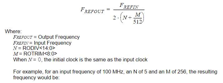
That's perhaps not as easy to understand. Let's see how it works. We have two variables:
- RODIV - Reference Clock Divider, which is a 15-bit number so can have a value from 0 to 32,767 and
- ROTRIM - Reference Clock Trim, which is a 9-bit number that can have a value from 0 to 511.
Whereas normal clocks just have a Divider, the Reference Clocks have a Trim variable to help provide fractional clock speeds. This means we can get much closer to our desired frequency than we can with timers. FREFIN refers to the frequency of the clock source we are using for the Reference Clock. This is defined by the ROSEL bits in REFOxCON:
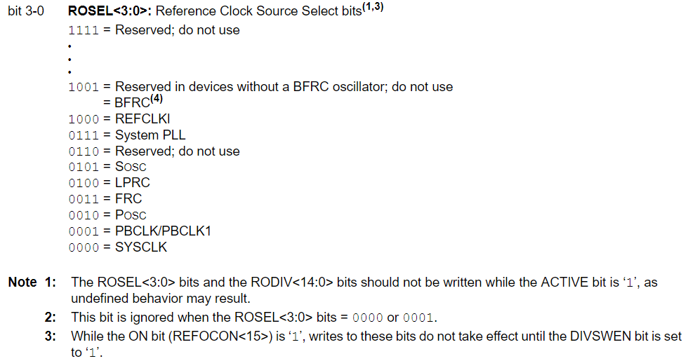
Phew. Lots of pictures today. Basically, when we're using the Reference Clock I'm going to be use PBCLK1 as the source and in all my example PBCLK1 is running at 100MHz.
To understand how setting the frequency works, let's look at how it works. For this example, we want an output frequency of 256 * 44,100Hz, or 11,289,600Hz:
- FREFOUT = FREFIN / [2 * (RODIV + ROTRIM/512)] can be rearranged to give us RODIV + ROTRIM/512 = FREFIN / (2 * FREFOUT).
- For us, that gives RODIV + ROTRIM/512 = 100,000,000 / (2 * 11,289,600), which is 4.4289.
- I will set RODIV to 4 and ROTRIM to (0.4289 * 512), which is 219.5968, so I'll round that up to 220.
Let's plug 4 and 220 back into the formula and see what we get out:
FREFOUT = FREFIN / [2 * (RODIV + ROTRIM/512)] so FREFOUT = 100,000,000 / [2 * (4 + 220/512)] = 100,000,000 / 8.859375 = 11,287,477Hz. Let's divide that to see what sample rate this translates to for our MP3 playback:
11,287,477 / 256 = 44,091Hz. That's only 9Hz off what we want, that's great. The Reference Clock Outputs all have a bit of error called jitter so they're not perfect but they're more than good enough for what we want to do.
BEWARE Something that tricked me when I first started working with the Reference Clock was that my frequency was frequently (har har) wrong. It turned out that this was the culprit:
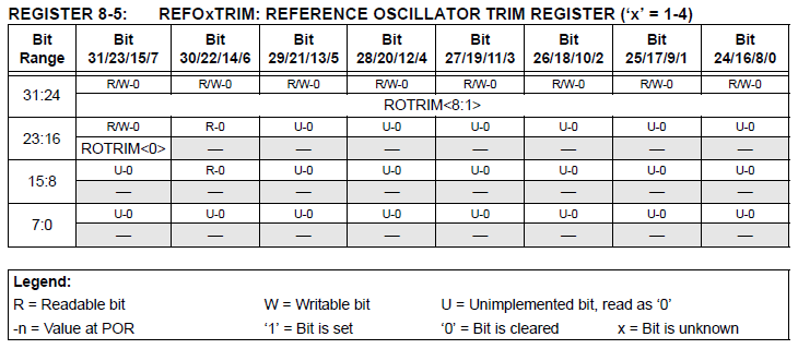
ONLY THE UPPER 9 BITS OF REFOxTRIM ARE USED. This means that when we set the Trim value, we must shift the value left by 23, like such:
REFO1TRIM = Trim << 23;
There is no separate REFOxDIV register, so this problem is avoided by using the named bits, like such:
REFO1CONbits.RODIV = div;
OK, back to regularly scheduled programming.
There's only one clock signal that we have yet to set up, and that's the SPI Clock.
Setting up the SPI Clock (SPICLK) to use the reference clock
If you'll recall, we're wanting to send stereo 44,100Hz 16-bit data to the DAC via I2S. Our Reference Clock Output (REFCLKO) is now outputting a signal that is 256 * 44,100. How fast does our signal need to be?
We want to send 16 bits (one 16-bit sample per left and right channel) 44,100 * 2 times a second because of stereo. So we need to be running at 88,200 * 16 = 1,411,200Hz. Thankfully, we don't have to set up yet another Reference Clock Output we can just use the SPI peripheral's built-in divider called the SPI Baud Rate Generator, or SPIBRG.
Our REFCLKO output is 256 x the sample frequency of 44,100 and we want our SPI signal to be (16+16) * 2, or 64 times 44,100. So let's do some easy maths for once: 256 / 64 = 4. The SPIBRG formula was:
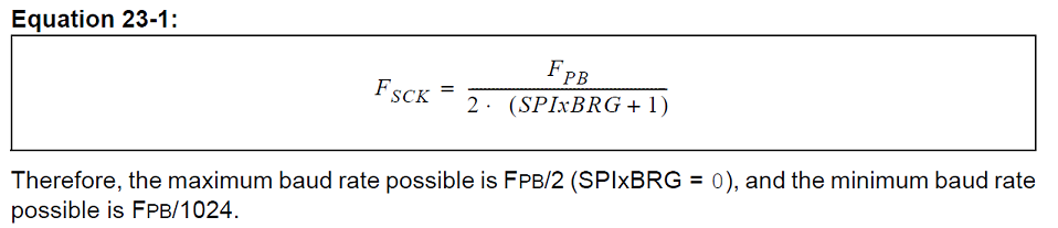
As we're dividing by 4, we want the bottom half of that fraction to be 4 so we will need to set SPIBRG to 1.
Setting up SPI audio mode
In my example, the pins will be connected as follows:
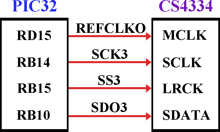
Note: The communication with this DAC is one way, we just send it data and it processes it automatically. So we don't need to use SDI3, we can disable it.
Let's take a look at how to initialise I2S on the PIC32MZ. It's actually laid out in the datasheet DS60001106 for us like this:
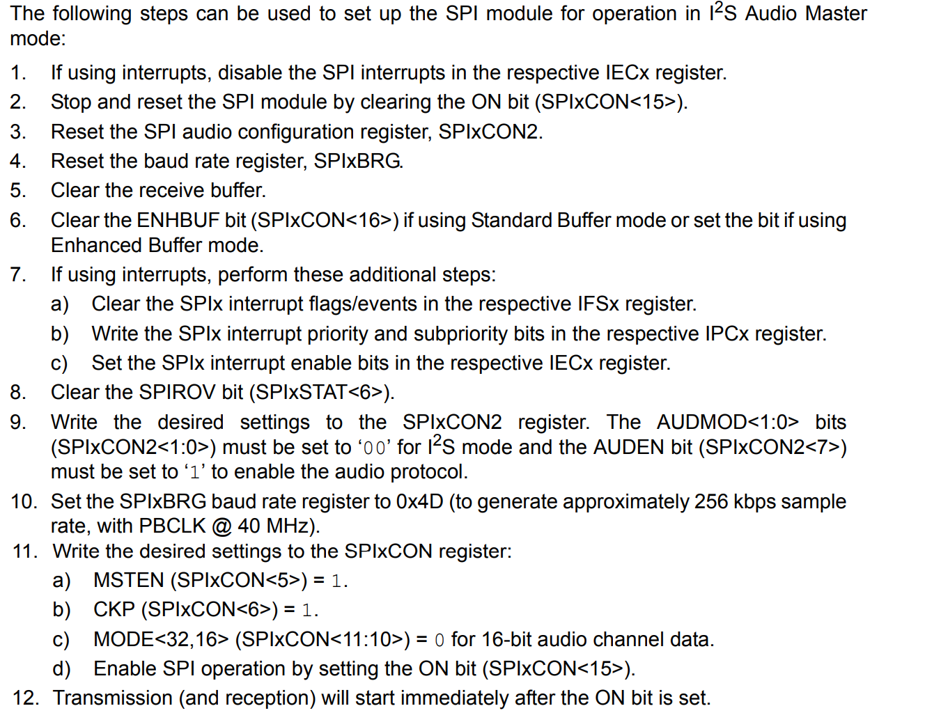
Let's see how that looks in C:
void I2S_init(int frequency)
{
    unsigned long int ref_freq; // The desired output frequency
    int div, trim;              // RODIV and ROTRIM
    float calc;             // Fractional values
    unsigned short dummy; // Used only to clear the data from SPI3BUF

    /* 1. If using interrupts, disable the SPI interrupts in the respective IECx register. */
    IEC4bits.SPI3TXIE = 0;

    /* 2. Stop and reset the SPI module by clearing the ON bit (SPIxCON<15>). */
    SPI3CONbits.ON = 0;
    /* 3. Reset the SPI audio configuration register, SPIxCON2. */
    SPI3CON2 = 0;
    /* 4. Reset the baud rate register, SPIxBRG. */
    SPI3BRG = 0;

    /* 5. Clear the receive buffer. */
    dummy = SPI3BUF;

    /* 6. Clear the ENHBUF bit (SPIxCON<16>) if using Standard Buffer mode or set the bit if using Enhanced Buffer mode */
    SPI3CONbits.ENHBUF = 1;

    /* 7. If using interrupts, perform these additional steps:
        a) Clear the SPIx interrupt flags/events in the respective IFSx register. */
    IFS4bits.SPI3TXIF = 0;

    /*  b) Write the SPIx interrupt priority and subpriority bits in the respective IPCx register. */
    IPC39bits.SPI3TXIP = 3;
    IPC39bits.SPI3TXIS = 1;

    /*  c) Set the SPIx interrupt enable bits in the respective IECx register. */
    IEC4bits.SPI3TXIE = 1;

    /* 8. Clear the SPIROV bit (SPIxSTAT<6>). */
    SPI3STATbits.SPIROV = 0;

    /* 9. Write the desired settings to the SPIxCON2 register. The AUDMOD<1:0> bits (SPIxCON2<1:0>) must be set to ?00? for I2S mode and the AUDEN bit (SPIxCON2<7>) must be set to ?1? to enable the audio protocol. */
    SPI3CON2bits.AUDEN = 1;     // Enable Audio mode
    SPI3CON2bits.AUDMONO = 0;   // Enable Stereo mode
    SPI3CON2bits.AUDMOD = 0;    // Type of audio mode is I2S
    SPI3CON2bits.IGNROV = 1;    // Ignore receive overflows
    SPI3CON2bits.IGNTUR = 1;    // Ignore transfer underruns

    /* 10. Set the SPIxBRG baud rate register */
    SPI3BRG = 1;                // Yields 64x the sample rate, for 16-bit stereo playback

    /* 11. Write the desired settings to the SPIxCON register:
        a) MSTEN (SPIxCON<5>) = 1. */
    SPI3CONbits.MSTEN = 1;
    /* b) CKP (SPIxCON<6>) = 1. */
    SPI3CONbits.CKP = 1;
    /* c) MODE<32,16> (SPIxCON<11:10>) = 0 for 16-bit audio channel data. */
    SPI3CONbits.MODE16 = 0;
    SPI3CONbits.MODE32 = 0;

    /* Additional settings needed for using the reference clock */
    SPI3CONbits.DISSDI = 1;     // Disable SDI pin
    SPI3CONbits.FRMPOL = 0;     // Frame pulse is active-low
    SPI3CONbits.CKE = 0;        // Serial output data changes on transition from idle clock state to active clock state
    SPI3CONbits.SMP = 1;        // Input data sampled at end of data output time
    SPI3CONbits.MCLKSEL = 1;    // PBCLK is used by the Baud Rate Generator

    /* Before turning on SPI3, let's set up the Reference Clock 1 (REFO1CLK) */

    // Set up REFO1CLK to be 256 x MIXER_FREQ and then times 2 again due to the formula
    calc = frequency * 256 * 2;

    // Calculate the values for RODIV and ROTRIM
    calc = (SYS_FREQ / 2 / calc); // At 44100Hz, this gives us 4.4288

    // Store the integer part in div (at 44100Hz, 4)
    div = (int)calc;
    // Subtract the integer part (at 44100Hz, 0.4288)
    calc -= div;
    // Multiply it by 512 to get it as a fraction of 512
    calc *=  512;
    // Store the integer part in trim
    trim = (int)calc;

    REFO1CON = 0;               // Reset the Reference Clock 1 configuration
    REFO1CONbits.RODIV = div;   // Set divider
    REFO1CONbits.ROSEL = 1;     // Source is PBCLK1
    REFO1TRIM = trim << 23;     // Shift the bits 23 places to the left

    // Enable the output of Reference Clock 1
    REFO1CONbits.OE = 1;
    // Turn on Reference Clock 1
    REFO1CONbits.ON = 1;

    // Turn on the SPI3 peripheral
    SPI3CONbits.ON = 1;
}
Boy, that is a lot of code. Something to be copy and pasted if ever such a thing existed :)
OK, now we've got SPI3 set up in I2S mode and it's being clocked by Reference Clock 1. Next, we need to write the interrupt handler:
void __attribute__((vector(_SPI3_TX_VECTOR), interrupt(ipl3soft), nomips16)) SPI3TX_handler()
{
    // Clear the SPI3 Transfer Interrupt Flag
    IFS4bits.SPI3TXIF = 0;

    SPI3BUF = playback_buffer[pb_readpos];

    // Increment the read position in the playback buffer
    pb_readpos++;

    // Check if the read position has exceeded the length of the playback buffer. If so, restart it at 0.
     if (pb_readpos >= PLAYBACK_BUFFER_SIZE)
         pb_readpos = 0;
}
That's very similar to the interrupt handler from last time so there's nothing much to discuss.
Final setup
The final thing to do is set all the PPS settings needed by this program:
// PPS for I2S outputs
RPD15R = 0b1111; // D15 = REFCLKO1
RPB10R = 0b0111; // B10 = SDO3
RPB15R = 0b0111; // B15 = SS3
Another difference is that we don't need to convert the 16-bit audio to 11-bit anymore, so we can just do this directly:
playback_buffer[pb_writepos] = MP3_OUTPUT_BUFFER[count];
The post before this one shows the benefits of using a proper, even if fairly cheap, DAC versus using PWM. Good luck and as always post any questions in the comments.
Categories: pic32