PMP and LCDs on the PIC32MZ post
Using the Parallel Master Port (PMP) to drive an LCD
OK, finally have my latest development board soldered and working. Today I will talk about using the PIC32MZ to drive an LCD. In my case, the LCD is a 7" 800x480 LCD with a SSD1963 LCD controller chip embedded in it. I got it from BuyDisplay, if anyone's interested. In short, today I want to show you how to do this:
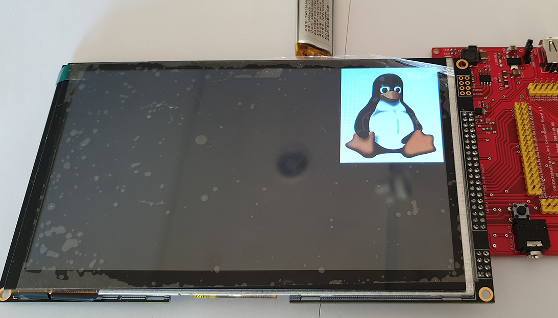
(Although hopefully you will have more sense than me and take the ugly screen protector off your LCD :) )
The Parallel Master Port (PMP) peripheral
So what is the PMP? Basically, it's an easy way to read or write lots and lots of data quickly to an external device. It can run in either 8bit or 16bit mode and supports up to a 16bit address so it's very useful for things like LCDs, cameras and external memory.
Important Note: In my example I'm using a separate Chip Select line and not making use of the internal PMCS1 and PMCS2. This is purely due to design limitations caused by the widely spaced layout of the PMP pins on the PIC32MZ.
<TL;DR>
But how is it different from just writing 16bits of data to LATB? The main difference is all the control signals that come with the PMP. The PMP provides two Chip Select (PMCS1 and PMCS2) lines, a Read Strobe (PMRD) and a Write Strobe (PMWR). This turns code like this:
// Send data
LATB = data;
// Toggle clock signal
LATASET = 1;
LATACLR = 1;
// Wait for LCD to be ready again
while (PORTAbits.RA1 == 1);
into this:
// Send data
PMDIN = data;
// Wait for LCD to be ready again
while(PMMODEbits.BUSY);
When you're talking about LCDs, like my 800x480 one, not having to manually handle clock signals can turn into a massive difference in throughput.
</TL;DR>
OK, let's get on with it. The important pins for PMP are:
- PMD0 to PMD15 - The data pins
- PMA0 to PMA15 - The address pins
- PMCS1 and PMCS1 - The two Chip Select pins
- PMWR and PMRD - The Write and Read strobe pins
Remember: The PMP runs off of Peripheral Bus Clock 2 (PBCLK2), so it will run at whatever speed that clock runs at
Here's how we initialise up the PMP:
    asm volatile("di");     // Disable all interrupts

    PMCONCLR = 0x8000;      // Turn PMP peripheral off before setting it up
    PMAEN = 0;              // Disable all address bits
    PMAENSET = 1;           // Enable Address Bit 0 (PMA0)

    PMCONbits.WRSP = 0;     // Set Write Strobe polarity to active low
    PMCONbits.RDSP = 0;     // Ret Write Strobe polarity to active low
    PMCONbits.PTRDEN = 1;   // Enable Read Strobe (RS)
    PMCONbits.PTWREN = 1;   // Enable Write Strobe (WR)
    PMCONbits.ADRMUX = 0;   // No MUXing please, all 16-bits on PMD<0:15>
    PMCONbits.SIDL = 0;     // Continue operation in idle mode
    PMCONbits.CSF = 00;     // PMCS2 enabled, PMCS1 is PMA14
    PMCONbits.ALP = 0;      // Set Address Latch Polarity bit active low
    PMCONbits.DUALBUF = 0;  // Disable Dual Buffer mode (use PMDIN and PMADDR registers)

    PMMODEbits.IRQM = 1;    // IRQ at the end of the Read/Write cycle
    PMMODEbits.MODE16 = 1;  // 16-bit mode
    PMMODEbits.MODE = 0b10; // Master mode 2
    PMMODEbits.WAITB = 3;   // Maximum wait / slowest speed
    PMMODEbits.WAITM = 15;  // Maximum wait / slowest speed
    PMMODEbits.WAITE = 3;   // Maximum wait / slowest speed
    PMMODEbits.INCM = 00;   // Do not automatically increment address when writing

    PMCONSET = 0x8000;      // Turn PMP peripheral on
    asm volatile("ei");     // Enable all interrupts again
I always initially set the PMP to the slowest speed before I initialise LCDs to counter some issues I've experienced. Once I've initialised the LCD I find I can set the PMP back to maximum speed with no issues.
<TL;DR>
Master mode 2? MUXing?
The PMP has two master modes, cleverly named mode 1 and mode 2. The main difference is that in mode 1, the RD/WR strobes are combined into a single signal and there's another signal called PMENB that determines whether there's a read or a write happening. In master mode 2, they are on two separate pins (namely PMRD and PMWR) and PMENB isn't used. My LCD has two separate pins for read and write strobes so I need to use master mode 2.
Multiplexing is a fancy way of either partially or fully using the same pins for address and data. This can save space but in turn takes longer to process because you have to handle some of the signals. For my LCD I don't need address bit (I just use PMA0 to control the data/command pin of my LCD) so I definitely don't want to use multiplexing.
</TL;DR>
Once you've set it up, it's incredibly simple to use the PMP:
- Wait for the PMP to be available
while(PMMODEbits.BUSY);
- Write data to the PMP
PMDIN = data;
Bam, done. And now, we move onto the fun of using this with LCDs.
Using the PMP to drive an LCD
Before starting, when you want to use an LCD with the PIC32MZ you need to know various things:
- What controller chip does your LCD use?
- Is it running in 8bit or 16bit mode?
- Does it work with 3.3V signals?
- What strobe (clock) signals does it need?
In my example, I have the following LCD:
- The controller chip is an SSD1963
- 16-bit mode
- Yes, it can run fine off of 3.3V signals and use 5V as a backlight supply
- It needs separate Read and Write strobes
All LCDs have their own special initialisation code that they need to be fed before they initialise. You can usually find this code on the Internet by googling, for example, "ssd1963 init". Another good resource is the excellent UTFT library source code. In my example, you can see the code for the SSD1963.
IMPORTANT: Please remember that your LCD may have a Chip Select (CS) line that usually needs to be set low for it to work at all. It may not work at all if you forget this!
Anyway, once your LCD initialises, it will usually look something like this (again, hopefully without that incredibly ugly, peeling off, bubbly plastic screen protector):
If you've gotten this far, well done. You're actually almost done! Most LCDs have some way of setting the area you want to draw to. With my LCD, I have to do this every time I want to draw something, it doesn't wrap around. Look in the controller chip's manual for something about setting window or setting area.
OK, let's display an image. I'm using one of Tux from Linux, which I hope is a free image. If not, please contact me and I'll draw something in mspaint. I hope not though because my mspaint skillz suck. I got the image from Wikipedia. Before we can use this image, we need to convert it into a 16bit image in RGB565 format. We can do this at the same website we get UTFT from. Choose to output a .c file and it'll turn your image into a 16-bit array.
#/media/File:Tux.svg)
<TL;DR>
RGB565 is a way of representing Red, Green and Blue (RGB) data in 16 bits, using 5 bits for Red, 6 bits for Green and 5 bits for Blue. It's very different to the 24-bit or higher colour displays we use on our computers and the colour numbers are not interchangable.
</TL;DR>
In my example, I've stored the data in an array called Tux. I draw the image on the screen like this:
    LCD_set_address(0,0,210-1,248-1);   // Tux image is 210 x 248 pixels, but we start at 0 so subtract 1 from each dimension
    LCD_write_command(0x2C);            // For the SSD1963 command 0x2C enables writing of pixel data
    PMADDR = 1;                         // PMADDR = 1 means writing data, not command
    for (cnt = 0; cnt < 210 * 248; cnt++)
    {
        PMP_wait();                     // Wait for the PMP to be free
        PMDIN = Tux[cnt];               // Send across 16bits of data
    }
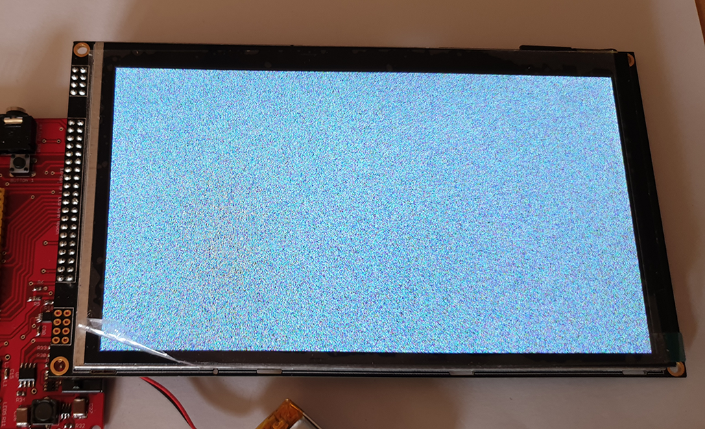
One more thing: Many of the LCDs I've messed with only seem to get re-initialised when you power them on and off again, so you may or may not see the grainy test pattern if you simply do a soft reset. YMMV. Using this method I've managed to store rather big 800x480 16-bit images in the PIC23MZ's internal flash (in an array) and write them across to the LCD without any visible flicker or delay, which is much better than some of the awful examples you can find on YouTube. Have fun and good luck!
Categories: pic32