DMA SD card reads on the PIC32MZ
Why read from SD card in DMA mode at all?
Warning: This post is going to be long because it's a complex topic and I've included lots of code in it.
Turns out the "next time" from last post was today, the same day. An entire day spent on writing about DMA and airing my ignorance online. Yay!
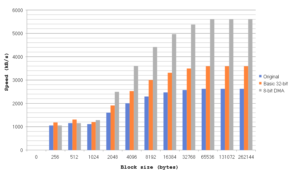
For the last several weeks / months / eternities I've been working on getting the DMA module to work with the SPI peripheral so that I can read from the SD card using DMA. My initial motivation for doing this was that when I had a few (i.e. too many) ISRs in my main code the SPI module would sometimes seem to get confused at all these interruptions and just stop working, crashing my program. However, DMA has also resulted in a nice large speed boost to SD reading, which is very useful. I've been working on this for ages in my spare time and I still don't understand all of it but today I'm going to go over my code and my findings. It works in my MP3 player and in large block transfers but I can't get over the feeling of mistrust I have for it so YMMV.
Reading from an SD card using DMA
Before we even get to using DMA, let's remind ourselves how the SD card works in SPI mode. For block reads, there is single block read mode and multi block read mode. Single block read mode needs to send the command to the SD card each time it wants to
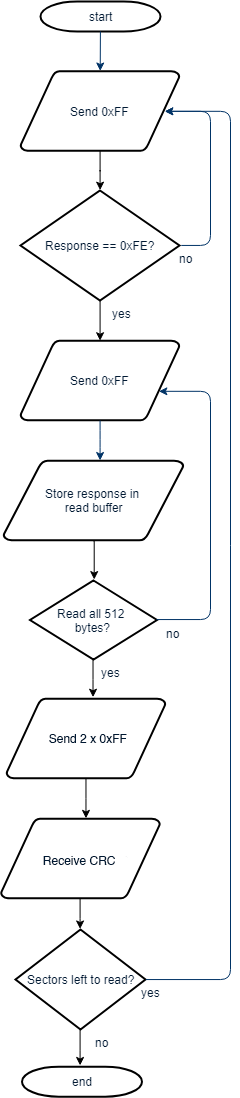
read a block. Multi block read sends a command once and then reads however many blocks it wants. Naturally, multi block read results in much faster transfer times than a single block read does. Don't forget that before the following flow chart, the SD card needs to be told
to set up the multi block transfer first. This code can be found in mmcpic32_dma.c in the disk_read() function. Once we've sent this command (and sector number and dummy CRC etc), the actual reading of the data works like this (click to enlarge):
(Shout-out to the website https://www.draw.io for providing a way to make flowcharts easily online, though with my drawing skills maybe they don't want people to know I used their site :))
So as you can (hopefully) see there are three phases to each 512-byte sector read:
- Send out 0xFF via SPI until the SD card replies with 0xFE
- Send out 0xFF and receive a data byte for each of the 512 bytes in the sector
- Send out 2 x0FF and receive the CRC to finish the sector read
After that, the process repeats until you have read as many sectors as are required. So how can we adapt this to make use of DMA? Well, let's think about what we need to do:
- Send 0xFF to the SD card over SPI
- Receive the data the SD sends us over SPI
In both of these cases, the PIC32MZ is the master and provides the clock signal to the SD card. This means the SD card cannot do anything unless we send it some data first. As you can see, there are two types of transactions here, the sending of the data and the receiving of the data. Assuming I'm using SPI Channel 2, without using DMA we would do this to send 0xFF to receive a byte of information from the SD card:
    SPI2BUF = 0xFF;
    while (SPI2STATbits.SPIRBE);
    data = SPI2BUF;
The overall flow of the program
OK, so one sending transaction and one receiving transaction means we will need to use two DMA channels. As I discussed last time, DMA channels need to be triggered by an Interrupt Request (IRQ), so what shall we choose? Again, let's think about the flow of this program:
- Send 0xFF to SD card
- Receive data in response
The SPI peripheral has both a transfer done (TX) and receive done (RX) IRQ that it generates, so this is perfect. I'm going to choose my two DMA channels as follows:
- DMA Channel 0 is in charge of receiving data from the SPI buffer
- DMA Channel 1 is in charge of sending data to the SPI buffer
This means that DMA Channel 0's start IRQ (SIRQ) will be SPI Channel 2's Receive Done IRQ (_SPI2_RX_VECTOR) and the source of DMA Channel 1's SIRQ will be SPI Channel 2's Transfer Done IRQ (_SPI2_TX_VECTOR). The _SPI2_RX_VECTOR is triggered whenever the SPI2 channel has finished
receiving a byte of data, and the _SPI2_TX_VECTOR triggers whenever the SPI2 channel has finished sending a byte of data.
This additionally means that the source address for DMA Channel 0 is the SPI Buffer SPI2BUF, because we are reading from that and the destination address of DMA Channel 1 is SPI2BUF because we are sending to it.
We are going to send 1 byte at a time (so cell size is 1), because we are using SPI in 8-bit mode. Perhaps we could get even more speed gains in 32-bit mode but we're fast enough for the moment.
We want to generate an interrupt when the transfer is done and I've chosen to use Interrupt Priority 4, Sub-priority 1.
Finally, I've chosen to abort DMA transfers whenever there's an error on SPI channel 2.
Before we move on, let's clarify what the heck we've been talking about and see how this is going to operate (click to enlarge):
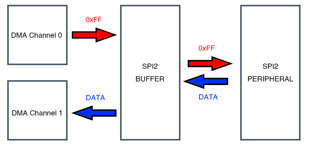
As should hopefully be clear thanks to that fantastic image, DMA Channel 0 and DMA Channel 1 are not talking to each other at all. DMA Channel 1 sends as many bytes as we tell it to to SPI Buffer 2 (SPI2BUF) until it's done and DMA Channel 0 receives as many bytes as we tell it to until it's done. This can be tricky to understand, so it bears further thought. When I send 0xFF to the SD card, what does it send in response? Due to the nature of SPI, it is sending the response to the last byte I sent it. Referring to the flow-chart above, when I'm waiting for the 0xFE token, I'm actually doing this:
    while (token != 0xFE)
    {
        SPI2BUF = 0xFF;
        while (SPI2STATbits.SPIRBE);
        token = SPI2BUF;
    }
When that's done, the SD card has already internally queued up the first byte of data to send to me, it just has no way of sending it to me. The next time I sent it an 0xFF, it will send me that queued up reply at the same time as I send it the 0xFF. What this means for my DMA approach is that when I send it 0xFF, the reply it sends me will be an answer to the previous 0xFF instruction. And then, because I've sent it 0xFF again it will have another byte of data prepared for me and will be waiting to send it. It will only be able to send me that data when I send it another 0xFF.
Secondly, looking at my fantastic picture of DMA data flow right above this, it becomes clear that we are going to make use of the SPI 2 Buffer. This means Enhanced Buffer Mode must be enabled for this to work at all. OK, theory out of the way, for now.
The happy news is that none of the above information ever changes, so we can set that all up once at the beginning of the program and never have to set it up again. I have done this in a function called SPI_DMA_init(), here's the code for it:
void SPI_DMA_init(void)
{
    DCH0SSA = virt_to_phys((void*)&SPI2BUF); // Source address
    DCH0ECONbits.CHSIRQ = _SPI2_RX_VECTOR;   // Trigger cell transfer event on SPI2 Receive IRQ
    DCH0ECONbits.CHAIRQ = _SPI2_FAULT_VECTOR;// Abort on SPI 2 error

    DCH0ECONbits.SIRQEN = 1;                 // Enable cell transfer event on IRQ
    DCH0ECONbits.AIRQEN = 1;                 // Enable cell transfer event on IRQ
    DCH0CONCLR = 1 << 4;                     // CHAEN = 0, turn off the abort enable
    DCH0CONSET = 3 << 16;                    // CHPRI = 3, set channel priority to 3

    DCH0SSIZ = 1;                            // Destination size is 1 byte
    DCH0CSIZ = 1;                            // Transfer 1 byte at a time

    DCH1DSA = virt_to_phys((void*)&SPI2BUF); // Destination address
    DCH1ECONbits.CHSIRQ = _SPI2_TX_VECTOR;   // Trigger cell transfer event on SPI2 Transmit IRQ
    DCH1ECONbits.CHAIRQ = _SPI2_FAULT_VECTOR;// Abort on SPI 2 error

    DCH1ECONbits.SIRQEN = 1;                 // Enable cell transfer event on IRQ
    DCH1ECONbits.AIRQEN = 1;                 // Enable cell transfer event on IRQ
    DCH1CONCLR = 1 << 4;                     // CHAEN = 0, turn off the abort enable
    DCH1CONSET = 2 << 16;                    // CHPRI = 2, set channel priority to 2

    DCH1CSIZ = 1;                            // Cell size
    DCH1DSIZ = 1;                            // Destination size

    IPC33CLR = 0b11111 << 16;                // Clear DMA1IP and DMA1IS bits
    IPC33SET = 0b10001 << 16;                // Interrupt Priority 4, Interrupt Sub-priority 1

    DMACONSET = 0x8000;                      // Enable DMA module if it hasn't been
}
You may be wondering why the Destination Size for channels 0 and 1 are set to 1. They can be set to the size of the actual transfer but the DMA module will see which one is bigger and use that anyway, so we can save having to repeat those two lines of code by doing it this way. As you'll see later, there's plenty more code to come.
Enough chat, plz give me teh codes tx
For the sake of a simpler explanation, I have made my multi block read function into a mini state machine. As a result, the code is fairly long and not as optimised as it could be but still yields good results. It looks like this:
static int rcvr_datablock_multiple(BYTE *buff, INT btr)
{
    unsigned char READ_DONE = 0;
    unsigned char READ_ERROR = 0;
    int DMA_sectors_left;
    char DMA_stage;
    int DMA_read_size;
    int DMA_bytes_left;
    BYTE crc[2];

    // Divide by 512 to get the number of 512-byte sectors to read
    DMA_sectors_left = btr >> 9;

    // Initialise the state machine
    READ_DONE = 0;
    DMA_BUSY = 0;
    DMA_stage = 0;
    READ_ERROR = 0;

    if (btr >= 512)
        DMA_read_size = 512; // Reading 512 bytes (one sector) at a time
    else
        DMA_read_size = btr; // Reading less than 512 bytes at a time

    // How many bytes do we need to read each time?
    DMA_bytes_left = btr;

    // Disable the SDO pin
    SPICONbits.DISSDO = 1;

    // Set the SDO pin to 1 so it will always output 0b11111111 (0xFF)
    SDO_PIN = 1;

    // Start waiting for the 0xFE token that precedes each sector read
    SPI_DMA_wait_token(buff, MAX_TOKEN_WAIT_BYTES);

    while (!READ_DONE)
    {
        while (DMA_BUSY)
        {
            // Could place a callback routine in here to do something while DMA is busy but haven't gotten around to that yet
        };

        switch (DMA_stage)
        {
            case 0: // Finished waiting for 0xFE token
            {
                if (DCH1SPTR > MAX_TOKEN_WAIT_BYTES)
                {
                    // 0xFE was not found in [MAX_TOKEN_WAIT_BYTES] bytes, give up
                    READ_DONE = 1;
                    READ_ERROR = 1;
                }
                else
                {
                    if (DMA_bytes_left > DMA_read_size)
                    {
                        SPI_DMA_read(buff, DMA_read_size);
                        DMA_bytes_left -= DMA_read_size;
                    }
                    else
                    {
                        SPI_DMA_read(buff, DMA_bytes_left);
                        DMA_bytes_left = 0;
                    }

                    DMA_stage = 1;
                }
                break;
            }
            case 1: // Finished reading data
            {
                buff += DMA_read_size; // Increment buffer position by number of bytes read

                // Read the CRC data now
                SPI_DMA_read(crc, 2);

                DMA_stage = 2;
                break;
            }
            case 2: // Finished reading CRC
            {
                DMA_sectors_left--;

                if (DMA_sectors_left > 0)
                {
                    // Restart the process
                    DMA_stage = 0;
                    SPI_DMA_wait_token(buff, 8192);
                }
                else
                {
                    READ_DONE = 1;
                }

                break;
            }
        }
    }

    // Reset everything
    DMACON = 0;
    SPICONbits.DISSDO = 0;

    if (READ_ERROR)
        return 0;
    else
        return 1;
}
OK, I realise that's pretty long so let's break it up into sections.
Initialising all the variables used and starting the wait for the 0xFE token
// Divide by 512 to get the number of 512-byte sectors to read
DMA_sectors_left = btr >> 9;

// Initialise the state machine
READ_DONE = 0;
DMA_BUSY = 0;
DMA_stage = 0;
READ_ERROR = 0;

if (btr >= 512)
    DMA_read_size = 512; // Reading 512 bytes (one sector) at a time
else
    DMA_read_size = btr; // Reading less than 512 bytes at a time

// How many bytes do we need to read each time?
DMA_bytes_left = btr;

// Disable the SDO pin
SPICONbits.DISSDO = 1;

// Set the SDO pin to 1 so it will always output 0b11111111 (0xFF)
SDO_PIN = 1;

// Start waiting for the 0xFE token that precedes each sector read
SPI_DMA_wait_token(buff, MAX_TOKEN_WAIT_BYTES);
The one trick I used here, which I got from some microchip forum ages ago, is that as we need to output a constant 0xFF value, and this equates to 0b11111111 in binary, we can just disable the SDO pin of the SPI peripheral (by setting DISSDO to 1) and set the value of the port pin to 1 and it'll just output 1's. Pretty neat trick.
When I call SPI_DMA_wait_token() I decided to give it a maximum number of bytes to wait for, in my program it's 8192. The number of bytes it takes to receive 0xFE is not set and seems to differ between SD cards. Let's take a look at the code in that function:
// SPI_DMA_wait_token sends out 0xFF and waits for the 0xFE token to come in. It will send a maximum of [num_bytes] bytes
void SPI_DMA_wait_token(unsigned char *buffer, unsigned int num_bytes)
{
    DCH0CONCLR = 1 << 7;            // Disable DMA Channel 0
    DCH1CONCLR = 1 << 7;            // Disable DMA Channel 1

    DCH0DSA = virt_to_phys(buffer); // Destination address
    DCH0CONCLR = 1 << 4;            // CHAEN = 0
    DCH0CONSET = 3 << 16;           // CHPRI = 3
    DCH0INTCLR = 0xFF00FF;          // Clear all DMA Channel 0 interrupt enables and flags
    DCH0INTSET = 0x90000;           // Enable the CHBCIE interrupt for DMA channel 0
    DCH0DAT = 'þ';                  // Wait for 0xFE token
    DCH0ECONSET = 1 << 5;           // PATEN is enabled
    DCH0CONbits.CHPATLEN = 0;       // 8bit pattern

    DCH0DSIZ = num_bytes;           // Destination size is [num_bytes]

    DCH1SSIZ = num_bytes;           // Source size is [num_bytes]

    DCH1INTCLR = 0xFF00FF;          // Clear all DMA Channel 1 interrupt enables and flags
    DCH1SSA = virt_to_phys(buffer); // Source address

    IFS4CLR = 0b11 << 14;           // Clear SPI2RXIF and SPI2TXIF
    IFS4CLR = 1 << 6;               // Clear DMA1IF
    IEC4SET = 1 << 6;               // Set DMA1IE

    DCH0CONSET = 1 << 7;            // Enable DMA Channel 0
    DCH1CONSET = 1 << 7;            // Enable DMA Channel 1
    DCH1ECONSET = 1 << 7;           // Set CFORCE on

    DMA_BUSY = 1;                   // DMA_BUSY flag set to 1 indicating active transfer
}
As always, before we configure anything, turn if off. In this case, clearing the CHEN bit of DCH0CON and DCH1CON does this fine. We do not want to disable the entire DMA module while we do this because we have no idea what the other 6 channels are doing.
The code is as discussed in my previous post, even the pattern matching which is looking for the 8-bit character 'þ' (0xFE). As we have previously set up most of the registers, we don't need to keep setting them up again. I routinely clear all the interrupt enables
and flags in both DCH0INT and DCH1INT to avoid any potential problems they may cause. I am using the Channel Block Transfer Complete (CHBC) interrupt to tell me when the transfer is finished. The DMA_BUSY flag is my own internal flag that I wait for, to avoid hammering the DMA module's status bits and thus slowing down the transfer.
Once the 0xFE token is found, or MAX_TOKEN_WAIT_BYTES is exceeded, we will get to the next stage of the state machine.
Starting a 512-byte sector read
case 0: // Finished waiting for 0xFE token
{
    if (DCH1SPTR > MAX_TOKEN_WAIT_BYTES)
    {
        // 0xFE was not found in [MAX_TOKEN_WAIT_BYTES] bytes, give up
        READ_DONE = 1;
        READ_ERROR = 1;
    }
    else
    {
        if (DMA_bytes_left > DMA_read_size)
        {
            SPI_DMA_read(buff, DMA_read_size);
            DMA_bytes_left -= DMA_read_size;
        }
        else
        {
            SPI_DMA_read(buff, DMA_bytes_left);
            DMA_bytes_left = 0;
        }

        DMA_stage = 1;
    }
    break;
}
The first thing I do here is check the DMA Channel 1 Source Pointer to see how many bytes it actually sent before receiving 0xFE. If this exceeds MAX_TOKEN_WAIT_BYTES, I abort the transfer. If not, I check to see how many bytes I need to read and then call SPI_DMA_read(). Let's take a look at the code behind it:
// SPI_DMA_read sends out 0xFF and reads in the returned data into [buffer], for a total of [num_bytes] byte transfers
void SPI_DMA_read(unsigned char *buffer, unsigned int num_bytes)
{
    DCH0CONCLR = 1 << 7;            // Disable DMA Channel 0
    DCH1CONCLR = 1 << 7;            // Disable DMA Channel 1

    DCH0DSA = virt_to_phys(buffer); // Destination address
    DCH0INTCLR = 0xFF00FF;          // All flag and ints off
    DCH0INTSET = 0x80000;           // CHBCIE = 1
    DCH0DAT = 0xFFFF;
    DCH0ECONCLR = 1 << 5;           // PATEN is disabled

    DCH0DSIZ = num_bytes;           // Source size

    DCH1SSIZ = num_bytes;           // Source size

    DCH1INTCLR = 0xFF00FF;          // Clear all DMA Channel interrupt enables and flags
    DCH1SSA = virt_to_phys(buffer); // Source address

    IFS4CLR = 0b11 << 14;           // Clear SPI2RXIF and SPI2TXIF
    IFS4CLR = 1 << 6;               // Clear DMA1IF
    IEC4SET = 1 << 6;               // Set DMA1IE

    DCH0CONSET = 1 << 7;            // Enable DMA Channel 0
    DCH1CONSET = 1 << 7;            // Enable DMA Channel 1
    DCH1ECONSET = 1 << 7;           // Set CFORCE on

    DMA_BUSY = 1;
}
This code is almost exactly the same as SPI_DMA_wait_token(). The only difference is that it disables pattern matching. They could easily be combined into one function, I've chosen to separate them for clarity as this is already a long and complicated subject.
Once the transfer is done, DMA_BUSY is again cleared and we move on to the next stage of the state machine, reading the 2-byte CRC.
Reading for the CRC
case 1: // Finished reading data
{
    buff += DMA_read_size; // Increment buffer position by number of bytes read

    // Read the CRC data now
    SPI_DMA_read(crc, 2);

    DMA_stage = 2;
    break;
}
Nothing much to say here. The CRC is 2 bytes of data and it must be read before either finishing the transfer or waiting for the 0xFE token again.
Note: This could easily be combined into the last SPI_DMA_read() before reading CRC, but I've chosen not to do this for clarity.
Restarting the state machine if needed
case 2: // Finished reading CRC
{
    DMA_sectors_left--;

    if (DMA_sectors_left > 0)
    {
        // Restart the process
        DMA_stage = 0;
        SPI_DMA_wait_token(buff, MAX_TOKEN_WAIT_BYTES);
    }
    else
    {
        READ_DONE = 1;
    }

    break;
}
OK, we got the CRC. Do we have any more sectors left to read? If so, restart the wait for the 0xFE token again. In multi block reads, the first wait for the 0xFE token can requires hundreds or even thousands of 0xFF bytes to be sent while the SD card gets ready but subsequent waits for 0xFE usually require only a few to be sent. This is part of the reason multi block reads are much faster than single block ones.
Cleaning up
// Re-enable SDO
SPICONbits.DISSDO = 0;

if (READ_ERROR)
    return 0;
else
    return 1;
Don't forget to re-enable SDO or the SPI port is not going to work and you're going to spend hours debugging your code :)
As I've mentioned multiple times before, this code isn't perfect and it's still under development. It seems to be working so far but I wouldn't trust it in anything you truly care about. Again, the SD card SPI specification allows for a maximum of 25MHz, and my code is running at 50MHz so if you experience issues, that's the first place I'd look (set SPIBRG to 1 to get 25MHz).