Choosing which pins to use on a PIC32MZ project post
How I choose which pins to use on a PIC32MZ project
I got an interesting question in my comments yesterday asking how I go about choosing which pins to use when I do a PIC32MZ project. My answer is a bit long and I think it might be useful to other noobs like me so I'm releasing it as a post today. Please note: This isn't based on anything but my own experience with PIC32MZ projects, it is certainly not the only way to to things. It's just the way I do it myself.
Basically, I go through the following steps:
- List all peripherals I will need for the project
- Check which hidden secrets the peripherals have
- Check errata to make sure they all work
- Check which pins each peripheral needs
- Actually choose the pins
List all peripherals I will need for the project
In the example I was given, it was 2 x I2S (using an internally generated reference clock), 3 x UART, 2 x I2C and 2 x SPI on a 144-pin PIC32MZ EFG chip. Furthermore, while I2C and SPI peripherals can both be connected to multiple devices, in the interests of speed (and for the explanation) I'm going to connect each device to a separate SPI and I2C peripheral. The aim will be simple: to map these peripherals to GPIO pins in a way that makes layout easy.
Check which hidden secrets the peripherals have
All the peripherals have certain things that must be kept in mind when they are used. They're not really secrets at all but they may not be immediately obvious when you first set out to use them. For the example, the "hidden secrets" are as follows:
SECRET 1
I2C peripherals are fixed and cannot be moved. Furthermore, I2C SDA and SCL pins require a 4.7k pullup resistor in order for them to meet the I2C standard and work reliably.
SECRET 2
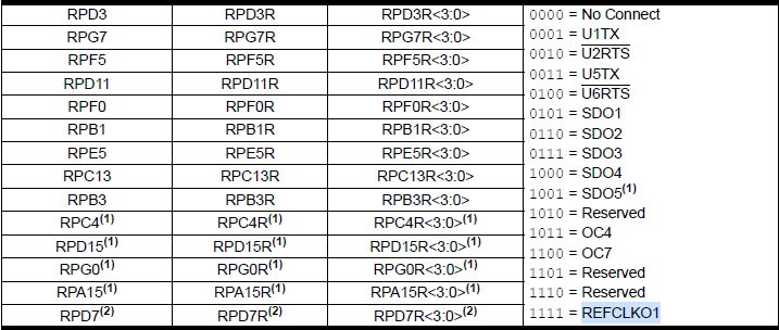
I2S either works off of PBCLK2 or off of REFCLKO1 because REFCLKO1 controls all SPI (which I2S is a subset of). It cannot just use any reference clock. For audio and the frequencies it uses, REFCLKO1 is much more useful. Furthermore, REFCLKO1 is set up by PPS, which further limits out options to the following:
SECRET 3
Although most pins for SPI peripherals can be moved around at will, the clock pins (SCK1 ~ SCK6) cannot be moved. Luckily, if we control the Chip Select (CS) pin of the device ourselves, we can gain a bit more flexibility.
SECRET 4
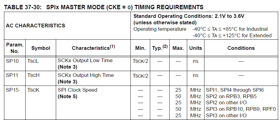
As I detailed in a post in the past, in order to extract 50Mhz from the SPI port you can only use SPI2 or SPI3 and even then only on specific pins, as follows:
Because of this, I'm going to be putting the SD card on SPI2 (but you could put the LCD there for 50Mhz too if you wish).
Check errata to make sure they all work
Unlike the 32MZ EC series, which was a horrible mess full of bugs, the EF series has relatively few errata. There is, however, one that looks concerning. It's listed as "The I2C module does not function reliably under certain conditions."
It turns out that this problem occurs when we use I2C at a rate of more than 100kHz and have constant I2C transfers of more than 500 bytes. The solution from Microchip, as it has been since the PIC32MX days, is to "bit bang". Which means to implement I2C by yourself and not use their peripheral. That's pretty poor.
In practice I haven't encountered this yet but it is something to bear in mind.
Amusingly, the UART has the following errata: "The UART automatic baud rate feature is intended to set the baud rate during run-time based on external data input. However, this feature does not function." Great work, Microchip. Great work.
Check which pins each peripheral needs
Straightforward stuff here. I'll list the ones relevant to my example.
Each SPI needs:
- MISO (SDI)
- MOSI (SDO)
- CS
- CLK
Each I2C needs:
- SDA
- SCL
Each UART needs:
- RX
- TX
Each I2S needs:
- MCLK (REFCLKO1)
- MOSI (SDO)
- SCK
- LRCK (for which I use Slave Select (SS))
Actually choose the pins
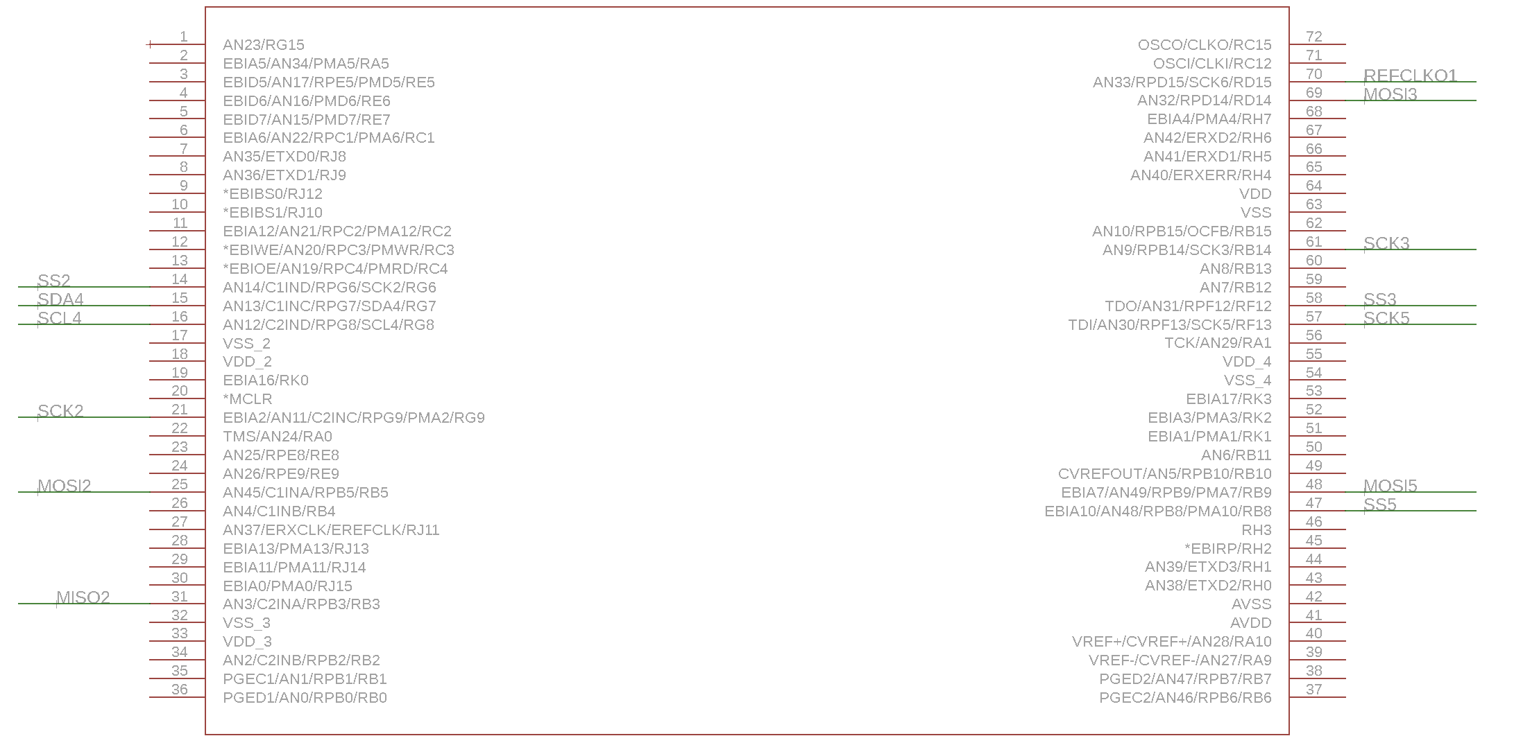
OK, now the part that we actually wanted to do. I like to keep the peripherals separated if possible to make layout easier as I routinely use double-sided boards. For this step I look at two parts of the datasheet, namely the pinout of the device and the PPS Input and Output sections. Bearing that in mind, for this example I'd use something like this:
First, on the one "side" of the PIC32MZ EF 144-pin devices, we have the RH and RK ports, which are totally useless from a PPS perspective. There are also no I2C peripherals on that particular side. However, there is a potential output for REFCLKO1 and three SPI peripherals, so I've put the two I2S ports there like this:
SPI3 (I2S):
- MOSI3 = RD14
- SCK3 = RB14
- SS3 = RF12 (used as LRCK)
- REFOCLK1 = RD15
SPI5 (I2S):
- MOSI5 = RB9
- SCK5 = RF13
- SS5 = RB8 (used as LRCK)
- REFOCLK1 = RD15
As noted earlier, I need two SPI peripherals and one of them must be on SPI2, using RB3 and RB5. There is one I2C peripheral on this same side. I've laid it out like this:
SPI2 (50Mhz):
- SCK2 = RG6
- MISO2 = RB3
- MOSI2 = RB5
- SS2 = RG9 (Chip Select)
I2C4:
- SDA4 = RG7
- SCL4 = RG8
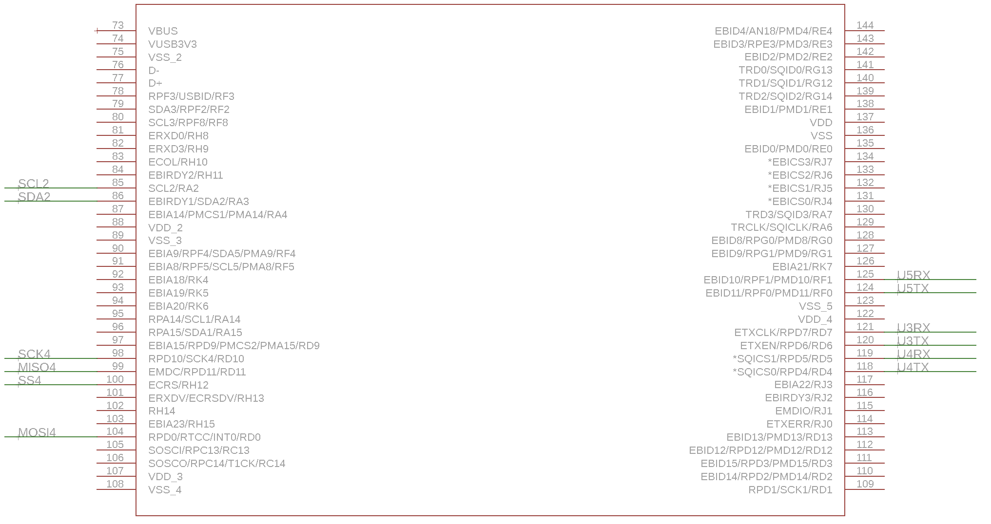
We still need one more I2C and one more SPI peripheral, which I've done as follows:
I2C2:
- SDA2 = RA3
- SCL2 = RA2
SPI4:
- SCK4 = RD10
- MISO4 = RD11
- MOSI4 = RD0
- SS4 = RH12 [See below]
I've chosen RH12 as SS4 (or Chip Select) but it cannot be used as SS4 in the PPS setting. I've done this because I plan to use this for the LCD, which needs me to manually control the Chip Select (CS) line and there are also no convenient PPS mappings for SS4 nearby.
OK, mostly done now. We now need 3 UARTs, which I've done as follows:
UART3:
- U3TX = RD6
- U3RX = RD7
UART4:
- U4TX = RD4
- U4RX = RD5
UART5:
- U5TX = RF0
- U5RX = RF1
In the end, it looks like this in Eagle (click to zoom):
Hope this will be of use to someone :)
Categories: pic32