Pulse Width Modulation (PWM) and servos on the PIC32MZ post
First, an update on why my timing has been off by a factor of two until now (doh!). It all comes down to this line:
PB7DIVbits.PBDIV = 1; // Peripheral Bus 7 Clock Divisor Control (PBCLK7 is SYSCLK divided by 1)
It was supposed to be this:
PB7DIVbits.PBDIV = 0; // Peripheral Bus 7 Clock Divisor Control (PBCLK7 is SYSCLK divided by 1)
I've gone and updated all the old source code, sorry for the dumb mixup :)
Additionally, I've finally started moving my source code to Github. If my site ever goes down, you can find the code here.
Using Pulse Width Modulation (PWM) on the PIC32MZ
Pulse Width Modulation (PWM) overview
Please note: In this post I'm just going to be talking about using PWM in order to send pulses of varying period, not in the context of creating a variable voltage output. So yes, there's a lot more to it than I'm going to cover today. On with the post!
Using the timer code from the last post (on timers), we can create an interrupt handler to give us a pulse like this:

That all happens in the background thanks to interrupts. However, the PIC32 series comes with a much better way to generate pulses, and it's all handled by the PIC32 in hardware. The module is called the Output Compare (OC) module, and it works as follows:
- It's attached to a specific timer
- When a timer ticks occurs, the value of the timer's count register (TMRxCNT) is compared to the value in the Output Compare Register (OCRx), and if TMRxCNT is bigger, one of several user-defined things can happen.
For today, we're looking at the PWM mode of the Output Compare module. What this does, is when the value TMRxCNT is lower than the value in OCRx, it sets the output OCx high. When TMRxCNT eventually gets bigger than OCRx, it sets the output OCx low. So how does this help us? Let's take a look at an example:
Say I want to generate a pulse that has a frequency of 1Hz (i.e. once every second) and I want to set port pin RC1 high for the first half and low for the second half of the pulse. Using an interrupt handler, I could do the following:
volatile int counter;

void init_timer2()
{
    T2CON   = 0x0;      // Disable timer 2 when setting it up
    TMR2    = 0;        // Set timer 2 counter to 0
    IEC0bits.T2IE = 1;  // Disable Timer 2 Interrupt

    // Set up the period. Period = PBCLK3 frequency, which is SYS_FREQ / 2, divided by 1000Hz and then divided by 8 for our chosen pre-scaler.
    PR2 = SYS_FREQ / 2 / 1000 / 8;

    // Set up the pre-scaler
    T2CONbits.TCKPS = 0b011; // Pre-scale of 8

    IFS0bits.T2IF = 0;  // Clear interrupt flag for timer 2
    IPC2bits.T2IP = 3;  // Interrupt priority 3
    IPC2bits.T2IS = 1;  // Sub-priority 1
    IEC0bits.T2IE = 1;  // Enable Timer 2 Interrupt

    // Turn on timer 2
    T2CONbits.TON   = 1;
    counter = 0;
}

void __attribute__((vector(_TIMER_2_VECTOR), interrupt(ipl3soft), nomips16)) timer2_handler()
{
    IFS0bits.T2IF = 0;  // Clear interrupt flag for timer 2
    counter++;
    if (counter < 500)
        LATCSET = 1;
    else
        LATCSET = 0;

    if (counter >= 1000) counter = 0;
}
And yes, that would work fine. However, it is unnecessarily complicated. With PWM it's much less code intensive because it's all handled in hardware. Let's take a look at that same code but using the Output Compare module in PWM mode:
void init_timer2()
{
    T2CON   = 0x0;      // Disable timer 2 when setting it up
    TMR2    = 0;        // Set timer 2 counter to 0

    /* Set up the period. Period = PBCLK3 frequency, which is SYS_FREQ / 2, divided by 1000Hz and then divided by 8 for our chosen pre-scaler. */
    PR2 = SYS_FREQ / 2 / 1000 / 8;

    // Set up the pre-scaler
    T2CONbits.TCKPS = 0b011; // Pre-scale of 8

    // Turn on timer 2
    T2CONbits.TON   = 1;

    OC6CON = 0;             // Turn off Output Compare module 6
    OC6CONbits.OCTSEL = 0;  // Interrupt source for this module is Timer 2
    OC6CONbits.OCM = 0b110; // Output Compare Mode (OCM) is 6, which is PWM mode
    OC6RS = SYS_FREQ / 2 / 1000 / 8 / 2;    // We want half the length of PR2
    OC6CONbits.ON = 1;      // Turn on Output Compare module 6 (OC6)
}
And that's it. Notice what's missing?We don't need to make an interrupt handler that wastes processing time and we don't even need to set up the interrupt for Timer 2. The PIC32's Output Compare module will handle it all for us! Let's take a look at the code:
OC6CONbits.OCTSEL = 0; // Interrupt source for this module is Timer 2
Output Compare Timer Select (OCTSEL) selects which timer to use as the source of interrupts. It can have either a 0 or 1 value, which will set it to Timerx or Timery. What does that mean? Let's look in the datasheet:
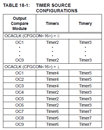
OK, as you can see, certain OC modules work with certain timers. Do not just assume they all work with Timer 2 or 3 :) In my example, OC6 works with Timer 2 (x) or Timer 3 (y) and I've set up Timer 2 already, so I set OCTSEL to 0.
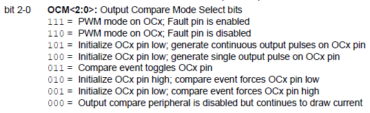
OC6CONbits.OCM = 0b110; // Output Compare Mode (OCM) is 6, which is PWM mode
Where does that come from? Again, the datasheet (beginning to see a pattern here?).
<TL;DR>
What's the difference between modes 6 and 7? There are two extra PPS pins available to the Output Compare modules, called OCFA and OCFB (Output Compare Fault A and B). When a 0 is detected on these pins, the output of the Output Compare modules will be disabled. This can be useful in certain situations, but I've never actually had need to use this for any of my simple programs. Therefore, I use mode 6 which has the fault pin disabled and stay away from mode 7 which has it enabled.
</TL;DR>
Next, set the Output Compare Register (OCR) value:
OC6RS = SYS_FREQ / 2 / 1000 / 8 / 2; // We want half the length of PR2
This is very similar to setting up the Period Register of the timer (PR2 in my case). I've set it to half the value of PR2.
IMPORTANT: Although the Output Compare module compares the value in OC6R to PR2, when writing the value we must write to the OC6RS register. It will then move the value over to OC6R itself on the next cycle.
OC6CONbits.ON = 1; // Turn on Output Compare module 6 (OC6)
That's pretty self explanatory.
IMPORANT: The Output Compare modules are set up using Peripheral Pin Select, so if you don't set them up they won't work at all. For example, to set port C1 to Output Compare module 6 (OC6), you would do this:
RPC1R = 0b1100; // Set RC1 to OC6
Remember, all of these PPS selections can be found in the PIC32MZ datasheet, currently in section TABLE 12-3: OUTPUT PIN SELECTION.
Using PWM to control an analog servo motor
I bought some PowerHD HD-1370A miniature servo motors from Banggood in order to make a very, very simple robot that can open and close its mouth. One of the things I always envied about Arduino users is that the code and libraries are all there for them. However, compared to the PIC32MZ the Arduino sucks in almost every way imaginable. Let's get this motor working with the PIC32MZ.
Servo motors usually require control signals to be sent in signals that are 20 milliseconds long. In general, the pulses themselves are between 1 and 2 milliseconds long, with 1 millisecond meaning turn as far clockwise as you can, 1.5 milliseconds meaning go to the mid-point (neutral) and 2 milliseconds meaning turn as far counter-clockwise as you can. The pulse is high for the duration and then for the rest of the 20 milliseconds it needs to go low again. This value of 1 to 2 milliseconds is very general and each motor has different requirements, so please always consult the motor's datasheet.
First, let's take a look at the datasheet for my motor:
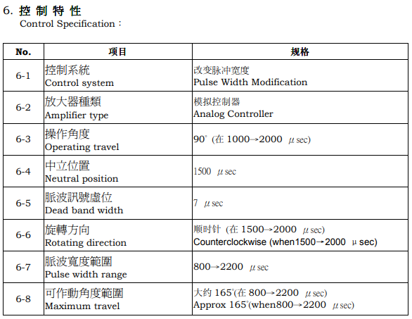
The numbers I care about there are the degrees it can travel, the pulse width range of 800us to 2200us and the neutral position of 1500us. So, in theory, if I send a control pulse that is high for 800us it will rotate clockwise as much as it can and if I send a pulse that is high for 2200us it will rotate counter-clockwise as far as it can go.
OK, so what I need:
- A timer that has a frequency of 50Hz (to give me 20ms / timer tick)
- A way of sending out a pulse that shifts between high and low during the 20ms period
- A way of setting the duty cycle (high/low time) of the control signal
Let's set up the timer first, using Timer 2. As always, let's check if this value fits in the Period Register (PR):
PR2 = SYS_FREQ / 2 / 1000 / 8 = 100,000,000 / 50 / 8 = 250,000
Nope. We need the value to be less than 65,536. A quick look at the possible pre-scaler values gives us 32, let's try plug that in:
PR2 = 100,000,000 / 50 / 32 = 62500
This works fine, so we need to set TCKPS to 0b101, which will give us a pre-scaler value of 32.
void PWM_init()
{
    T2CON   = 0x0;      // Disable timer 2 when setting it up
    TMR2    = 0;        // Set timer 2 counter to 0

    /* Set up the period. Period = PBCLK3 frequency, which is SYS_FREQ / 2, divided by 50 Hhz and then divided again by 32 for our chosen pre-scaler. */
    PR2 = SYS_FREQ / 2 / 50 / 32;

    // Set up the pre-scaler
    T2CONbits.TCKPS = 0b101; // Pre-scale of 32

    // Turn on timer 2
    T2CONbits.TON   = 1;

    OC6CON = 0;             // Turn off Output Compare module 6
    OC6CONbits.OCTSEL = 0;  // Interrupt source for this module is Timer 2
    OC6CONbits.OCM = 0b110; // Output Compare Mode (OCM) is 6, which is PWM mode
    OC6RS = 0;              // Keep the signal low for the entire duration
    OC6CONbits.ON = 1;      // Turn on Output Compare module 6 (OC6)
}
Now, let's calculate how to send a 1000us long high pulse. The Period Register value of 62500 represents the full 20ms long signal. Let's use that to work out the value we need to put into OC6RS:
(1 / 20) * 62500 = 0.05 * 62500 = 3125
There are ways to have it slightly more accurate in cases where the number is fractional, but for now let's try that out and see what happens:
/* in main() */
OC6RS = 3125;               // Move servo to 1ms position
Let's see what we get on the scope:

OK, excellent. The period of the signal is 20ms, let's zoom in on that pulse though and see if it's 1ms:

Hooray, we have what we want. So plugging my servo motor's signal pin into this wire (along with giving it Vcc and Ground of course) will result in the servo moving to the position I want it to. You can even get it to move between positions easily now:
/* in main() */
while (1)
{
    OC6RS = 3125;       // Move servo to 1ms position
    delay_ms(1000);
    OC6RS = 6250;       // Move servo to 2ms position
    delay_ms(1000);
}
Remember, all servos are different and require different timing. Especially if you're like me and source them from AliExpress, Banggood and eBay. The motors found there are often clones and have slightly different timing to the originals. Good luck!
Categories: pic32