SPI on the PIC32MZ post
What is SPI and how do we use it on the PIC32MZ?
Last time I covered Peripheral Pin Select, and this is something that will be needed in today's post about using SPI so if you don't know about it I suggest you read the previous post first.
SPI or Serial Peripheral Interface is a way of communicating with an external device using 3 or 4 wires, depending on whether we way one-way or two-way communication. A simple look in the infamous PIC32 datasheet under SPI reveals yet another extra datasheet we need to download, in this case entitled DS60001106. So fine, we download that and look at what pins SPI uses and we eventually get to this:
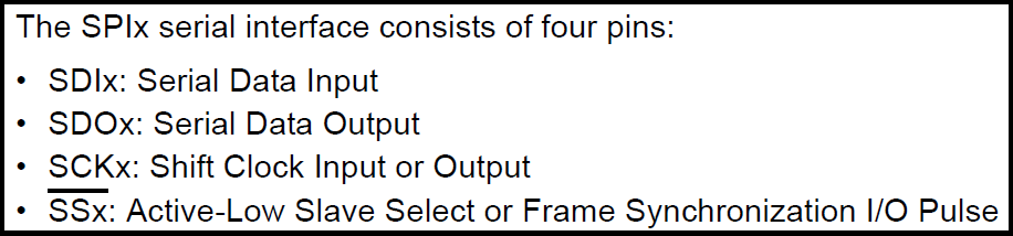
With SPI, there is a Master device and a Slave device. The master device is the one that controls the transaction and needs to send a clock signal to the slave device. If you come from Arduino the naming is a little different:
- SDI here means data into the PIC32 from some other device and in my example would also be known as MISO (Master In, Slave Out)
- SDO means data out of the PIC32 and to another device and in my example would also be known as MOSI (Master Out, Slave In)
- SCK is the clock signal and the name is pretty common across all platforms.
- SS is slave select, also known as CS (Chip Select).
An important thing to remember about SPI is that the master is the only one that can generate the clock signal. This means that if you want to get device from an SPI module or SD card or whatever, you have to send it data in order for it to get the clock signal it needs to send you some data back. The sending and receiving of data is done at the same time becaue there is a dedicated wire for each (namely, SDI and SDO). For example, let's look at the following scenario: I have an 8-bit SPI connected LCD, and I want to read pixel 1 from its display memory. The command to do this is 0xFE followed by the pixel number, which is 0x0001 (a 16-bit number). I'd send the following data:
- Send 0xFE, ignore reply.
- Send 0x00, ignore reply.
- Send 0x01, ignore reply.
Now the slave device has the command and the parameter, it needs time to process the data before it can respond. Some devices can do this instantly, but some need a few clock cycles in order to process it because they depend entirely on this clock signal to operate at all. In my example, the LCD needs 3 clock cycles before it can reply with a 16-bit number. So to give it three cycles, I need to send it dummy data. I've chosen to send 0xFF and it may be different depending on the peripheral but everything I've seen was fine with 0xFF. So now we have to:
- Send 0xFF, ignore reply.
- Send 0xFF, ignore reply.
- Send 0xFF, ignore reply.
OK, now the LCD is ready to send me a 16-bit number back. I'm in 8-bit mode so this means 2 clock cycles.
- Send 0xFF, store reply as high 8-bits.
- Send 0xFF, store reply as low 8-bits
- Combine words: result = (high << 8) | low;
So a simple transaction can actually take a long time. This is how all SPI transactions work, and needs to be kept in mind.
One of the cool things about SPI is we can attach multiple devices to the SDI, SDO and SCK wires at the same time. With this system, each attached device would need a dedicated Chip Select pin of its own. For example, RA0 could be chip select for an SD memory card, RA1 could be chip select for an SPI LCD, etc. Because of this, in most of my SPI projects where the PIC32 is acting in the role of master I do not use the SPI peripheral's SS pin I just assign it to whichever port is convenient to me. Note: In I2S (Inter-IC Sound) we usually have to use the SS pin as it generates a special clock signal. That's beyond the scope of today's blog post however.
This is going to be a two-part post and the eventual goal is to attach an SD card to my PIC32MZ and read the first 128 bytes from a file named "test.txt" in the root directory. We will be making use of the excellent FatFs library - available here - to access and read the file so the SD card must be FAT or FAT32 formatted. This is actually quite an involved process so today I'm just going to look at setting up and using the SPI peripheral.
OK phew, explanation of what we want to do out of the way, let's move on to choosing which pins we want to use the SPI peripheral on. After all, according to the datasheet there are "Six 4-wire SPI modules (up to 50 MHz)" so we're spoiled for choice. And if you believe that, you haven't been burned by PIC32MZ badly enough yet (or haven't been shopping). Way, waaaaaay down in the datasheet you'll see why it says "up to 50Mhz."
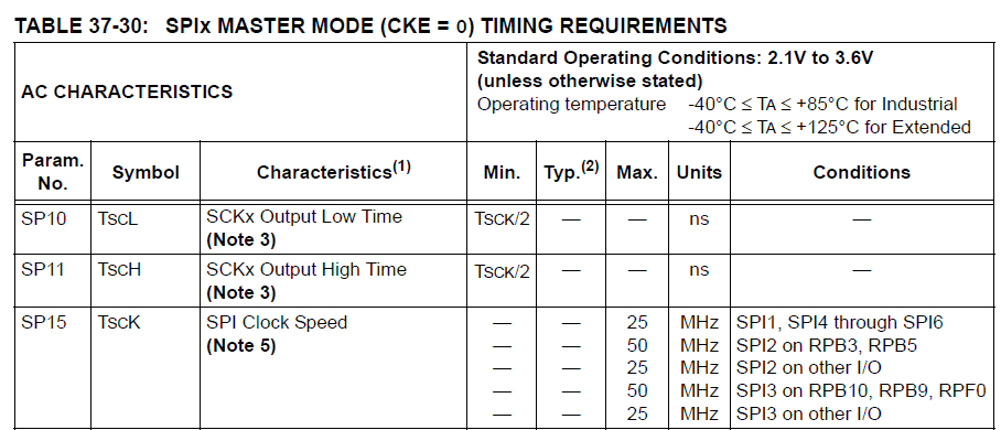
Waaah Waah Waah Waaaaaaaaah. Oh, and let's not forget that little note number 5!
"5: To achieve maximum data rate, VDD must be ≥ 3.3V, the SMP bit (SPIxCON<9>) must be equal to ‘1’, and the operating temperature must be within the range of -40°C to +105°C."
And let me guess, additionally, it must be the night of the second full moon of the month and between 9PM and 11PM on a Tuesday, right? Naturally, we want to access the SD card at 50Mhz and not 25Mhz. Nothing is ever easy and straightforward with the PIC32MZ. Anyway, in my example I'm going to be using SPI2, with SDI on RB3, SDO on RB5 and CS on RB4. The SCK2 pin is not movable via Peripheral Pin Select, and on the 144-pin chip I use it is always on pin 14 (RG6). OK, let's set up PPS for SDO2 and SDI2:
SDI2R = 0b1000; // RB3 = SDI2
RPB5R = 0b0110; // RB5 = SDO2

TRISBbits.TRISB3 = 1; // Set RB3 as input because it's SDI2
PPS out the way, let's look at actually setting up SPI2 peripheral. On the PIC32MX with PLIB we used to do this:
SpiChnOpen(SPI_CHANNEL2,SPI_OPEN_MSTEN | SPI_OPEN_CKP_HIGH | SPI_OPEN_SMP_END | SPI_OPEN_MODE8, 64);
If you want to do this on the PIC32MZ, there is no PLIB so you can use the following code to do the same thing, with one small difference:
void SPI_init()
{
    SPI2CONbits.ON = 0; // Turn off SPI2 before configuring
    SPI2CONbits.MSTEN = 1; // Enable Master mode
    SPI2CONbits.CKP = 1; // Clock signal is active low, idle state is high
    SPI2CONbits.CKE = 0; // Data is shifted out/in on transition from idle (high) state to active (low) state
    SPI2CONbits.SMP = 1; // Input data is sampled at the end of the clock signal
    SPI2CONbits.MODE16 = 0; // Do not use 16-bit mode
    SPI2CONbits.MODE32 = 0; // Do not use 32-bit mode (combines with the above line to activate 8-bit mode)
    SPI2BRG = 0; // Set Baud Rate Generator to 0 [discussed below]
    SPI2CONbits.ENHBUF = 0; // Disables Enhanced Buffer mode [also discussed below]
    SPI2CONbits.ON = 1; // Configuration is done, turn on SPI2 peripheral
}
This will setup the SPI2 port as a master in 8-bit mode at 50Mhz using the standard polarities devices expect. For more explanation, we turn to...
<TL;DR>
The SPI2BRG register controls the speed of the SPI peripheral, and it is controlled by the following formula from the manual:
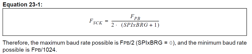
A while ago I discussed how different peripheral bus clocks control different peripherals. In this case, Peripheral Bus Clock 2 controls both the UART and the SPI. We set the peripheral bus clock 2 to 100Mhz during the initialisation. The smallest we can set SPI2BRG to is 0, which means the fastest speed we can get is (100/2*(0+1)), which is 100/2 which is 50Mhz. Every time the clock signal changes from high to low a bit is transmitted/received, so let's look at the actual byte transfer rates we can expect. We have a maximum of 50Mbps in 8-bit mode, which is 50mbps / 8 = 6.25MB/s at an absolute maximum, though in reality we won't be getting near this rate and I've found we usually get somewhere around 4MB/s reliably with my file transfers.
The Enhanced Buffer mode enables a 16-byte deep FIFO (First In First Out) buffer, which enables us to load up 16 bytes of data before the sending even begins. In practice this saves a huge amount of time and gives us faster transfer rates because the SPI peripheral has less time when it is doing nothing and just waiting for us to give it data to send.
</TL;DR>
OK, SETUP IS DONE! Now how do we use it to send data? Thankfully, its dead simple to use. If we want to send a character stored in the data variable to SPI2 we can do it like this:
char SPI_send(char data)
{
    SPI2BUF = data; // Send **data** to SPI2BUF.
    while (SPI2STATbits.SPIRBE); // Which the receive buffer is empty, loop
    return (char)SPI2BUF; // Return whatever is in SPI2BUF
}
<TL;DR>
A note on Enhanced Buffer Mode: We don't use SPI2STATbits.SPIRBE when in enhanced buffer mode, instead we check the value of SPI2STATbits.RXBUFELM, which tells us how many elements (bytes) are stored in the receive buffer. If I send 16 bytes like this:
int cnt;
for (cnt = 0; cnt < 16; cnt++)
{
    SPI2BUF = 0xFF;
}
The SPI2 peripheral will start sending data. At the very beginning, the value of SPI2STATbits.TXBUFELM will be 16 because it has 16 bytes queued up, and the value of SPI2STATbits.RXBUFELM will be 0 because it hasn't received anything yet. As it process the 16 bytes automatically, eventually SPI2STATbits.TXBUFELM will move down to 0. As it moves down to 0, SPI2STATbits.RXBUFELM will move up to 16 as it receives the replies. I can then read the data as follows:
int cnt;
char data[16];
for (cnt = 0; cnt < 16; cnt++)
{
    data[cnt] = SPI2BUF;
}
As soon as I read from SPI2BUF, the peripheral automatically removes the top entry from the buffer, puts the next value in SPI2BUF and reduces RXBUFELM by 1.
</TL;DR>
A very important note about the timing of sending and receiving data
When we send data via SPI, we always get some data back immediately but it is vital that you remember this reply data is actually the reply to the previously sent data byte. For most transactions, this doesn't matter. We often just want to send tons of data and the replies from the slave device are not important. However, when we are working with something where the replies are important, this can be a potentially dangerous trap. As such, there are a lot of "dummy" bytes sent in SPI transactions in order to give the slave the clock signals it needs to reply, and the dummy bytes are often 0xFF.
Wow, that was way more complicated that I intended it to be. Next time we'll use this code and understanding of SPI to communicate with an SD card.
Categories: pic32