Configuration without Harmony 1 post
How to configure the PIC32MZ to run at 200Mhz
TL;DR warning: This goes into quite a lot of detail and you can just download the code at the bottom of the page and it'll work fine. However, the reason for having this blog was to share why we set things to the values we do so here goes!
One of the biggest problems with the PIC32 series is that the startup configuration sucks. Everything seems to be set to low speeds, all the digital ports are set to analog and nothing is how you generally want it to be. So we need to set up the configuration "fuses" (just another name for setting) before we even begin to code. Today I'm purely going to be focussing on how to get the chip running at the frequency we want because it's long enough that it deserves a post of its own. For my example, I'm using a PIC32MZ2048EFF144, but this configuration applies to any PIC32MZ chip, and is very similar to PIC32MX configuration settings. In my example, I'm using a 24Mhz External Clock and I want the chip to run 200Mhz so I set the relevant fuses as follows:
#pragma config FPLLIDIV = DIV_3         // System PLL Input Divider (3x Divider)
#pragma config FPLLRNG = RANGE_5_10_MHZ // System PLL Input Range (5-10 MHz Input)
#pragma config FPLLICLK = PLL_POSC      // System PLL Input Clock Selection (POSC is input to the System PLL)
#pragma config FPLLMULT = MUL_50        // System PLL Multiplier (PLL Multiply by 50)
#pragma config FPLLODIV = DIV_2         // System PLL Output Clock Divider (2x Divider)
#pragma config POSCMOD = EC             // Primary Oscillator Configuration (External clock mode)
#pragma config FNOSC = SPLL             // Oscillator Selection Bits (System PLL)
While it initially seems like a lot to take in, it's not that bad. Let's look at it line by line.
#pragma config FPLLIDIV = DIV_3 // System PLL Input Divider (3x Divider)
I start with my 24Mhz clock frequency and I set the input divider to 3. This means the PLL input frequency will be 24 / 3 = 8Mhz.
#pragma config FPLLRNG = RANGE_5_10_MHZ // System PLL Input Range (5-10 MHz Input)
This next line tells the PIC32MZ what range this frequency is in, and 8Mhz fits nicely into the 5 to 10Mhz range.
#pragma config FPLLICLK = PLL_POSC // System PLL Input Clock Selection (POSC is input to the System PLL)
This tells the PIC32MZ where the clock signal is coming from. If you have connected an external clock or a crystal, this will be set to POSC (which is short for Primary Oscillator).
#pragma config FPLLMULT = MUL_50 // System PLL Multiplier (PLL Multiply by 50)
This is where the magic begins. The PIC uses something called a PLL (or Phase Locked Loop) to multiply the frequency we put into it, allowing us to run at very high speeds with a lower input frequency. So I've set the multiplier to 50, which means by 8Mhz will now be 400Mhz. However, this is too high for the PIC32MZ chip I use, which can only do 200Mhz maximum, so we need to do one final configuration for frequency.
#pragma config FPLLODIV = DIV_2 // System PLL Output Clock Divider (2x Divider)
This will tell the PIC32 to divide whatever frequency is coming out of the PLL (which was 400Mhz in our example) and divide it by 2, giving us the frequency we wanted, which is 200Mhz.
#pragma config POSCMOD = EC // Primary Oscillator Configuration (External clock mode)
This tells the PIC32MZ that I'm using an External Clock. If you're using a crystal, this value will be XT or HS, depending on whether you're using a lower speed (3 to 10Mhz) crystal (XT) or a higher speed (10 to 20Mhz) crystal (HS). However, I strongly recommend using an external clock with the PIC32MZ as there are still errata related to the crystal and I've had issues where things didn't work right. So while the external clock is a little bit more expensive ($0.50 or so more) I'd say go for it by all means.
#pragma config FNOSC = SPLL // Oscillator Selection Bits (System PLL)
Finally, seting Oscillator Selection to System PLL. You could set this to an external clock but then why did we set all that up in the beginning?
Note: The procedure for setting up the 8Mhz internal "FRC" clock is very similar, you just need to make the following changes:
#pragma config FPLLIDIV = DIV_1         // System PLL Input Divider (1x Divider)
#pragma config FPLLRNG = RANGE_5_10_MHZ // System PLL Input Range (5-10 MHz Input)
#pragma config FPLLICLK = PLL_FRC       // System PLL Input Clock Selection (FRC is input to the System PLL)
#pragma config FPLLMULT = MUL_50        // System PLL Multiplier (PLL Multiply by 50)
#pragma config FPLLODIV = DIV_2         // System PLL Output Clock Divider (2x Divider)
#pragma config POSCMOD = OFF            // Primary Oscillator Configuration (Primary Oscillator disabled)
I'm using an external clock because the FRC is sadly not accurate enough to allow for using the USB module. It's perfectly fine for most projects not using USB, however.
So we're done right? 200Mhz set, time to go! Sadly, no. That's the easy part. We now need to set up the frequency of the various peripheral clocks, turn on caching and turn on pre-fetch. When we had the PIC32MX series and used PLIB, this was done by simply calling SYSTEMConfigPerformance(80000000UL). Thanks to Harmony, we don't have access to this any more and have to write it for ourselves. Fun. There are eight peripheral clocks on the PIC32MZ EF series, and if you look in the data sheet you get this helpful diagram.
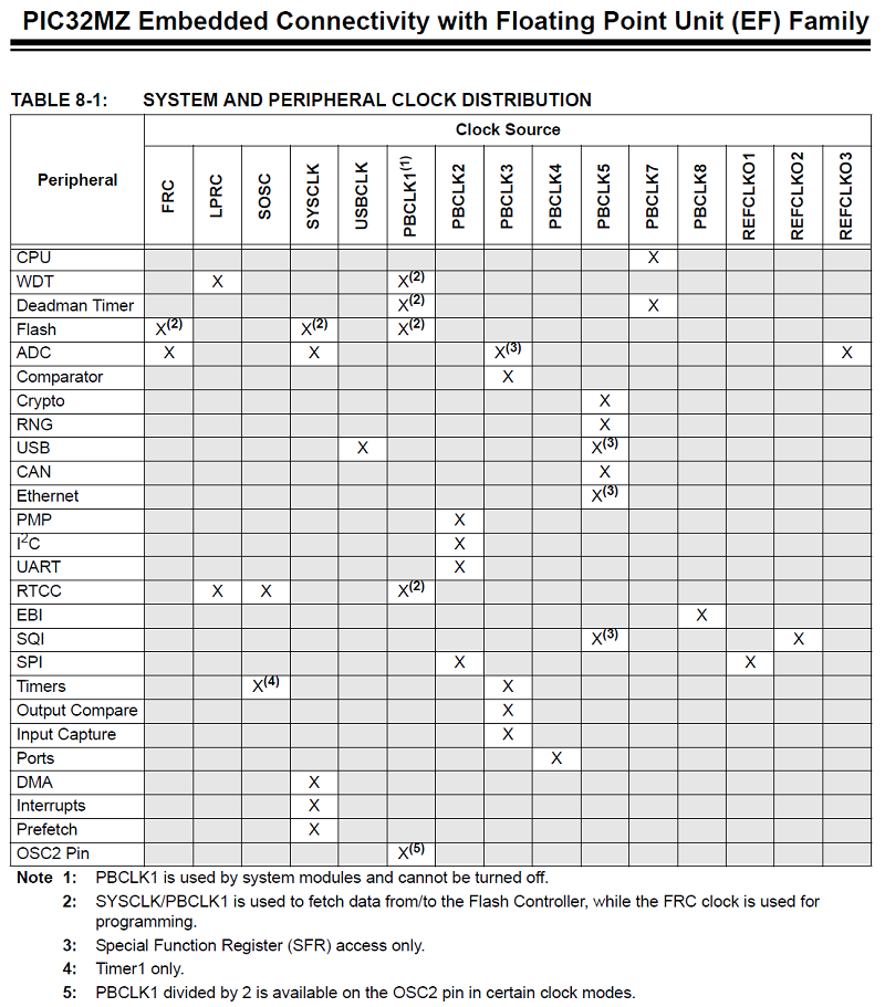 This is a very important, if initially confusing, diagram telling us which of the Peripheral Bus Clocks (PBCLKs) are responsible for which peripherals. I will refer to this diagram a lot when discussing various peripherals later on, it's well worth keeping in mind. Even later in the datasheet, you'll come across this
0000001 = PBCLKx is SYSCLK divided by 2 (default value for x ~~=~~ 7)
0000000 = PBCLKx is SYSCLK divided by 1 (default value for x = 7)
on the page about PBxDIV. What this essentially means is that all of the peripheral bus clocks are limited to a maximum speed of our system clock (SYSCLK, which is 200Mhz in my example) divided by 2. Except for PBCLK4 and PBCLK7, which are responsible for the Ports and CPU and the Deadman Timer respectively. For us hobbyists, we often just want stuff to run as fast as it can, so here's the function I wrote to set everything to maximum.
void set_performance_mode()
{
    unsigned int cp0;

    // Unlock Sequence
    asm volatile("di"); // Disable all interrupts
    SYSKEY = 0xAA996655;
    SYSKEY = 0x556699AA;

    // PB1DIV
    // Peripheral Bus 1 cannot be turned off, so there's no need to turn it on
    PB1DIVbits.PBDIV = 1; // Peripheral Bus 1 Clock Divisor Control (PBCLK1 is SYSCLK divided by 2)

    // PB2DIV
    PB2DIVbits.ON = 1; // Peripheral Bus 2 Output Clock Enable (Output clock is enabled)
    PB2DIVbits.PBDIV = 1; // Peripheral Bus 2 Clock Divisor Control (PBCLK2 is SYSCLK divided by 2)

    // PB3DIV
    PB3DIVbits.ON = 1; // Peripheral Bus 2 Output Clock Enable (Output clock is enabled)
    PB3DIVbits.PBDIV = 1; // Peripheral Bus 3 Clock Divisor Control (PBCLK3 is SYSCLK divided by 2)

    // PB4DIV
    PB4DIVbits.ON = 1; // Peripheral Bus 4 Output Clock Enable (Output clock is enabled)
    while (!PB4DIVbits.PBDIVRDY); // Wait until it is ready to write to
    PB4DIVbits.PBDIV = 0; // Peripheral Bus 4 Clock Divisor Control (PBCLK4 is SYSCLK divided by 1)

    // PB5DIV
    PB5DIVbits.ON = 1; // Peripheral Bus 5 Output Clock Enable (Output clock is enabled)
    PB5DIVbits.PBDIV = 1; // Peripheral Bus 5 Clock Divisor Control (PBCLK5 is SYSCLK divided by 2)

    // PB7DIV
    PB7DIVbits.ON = 1; // Peripheral Bus 7 Output Clock Enable (Output clock is enabled)
    PB7DIVbits.PBDIV = 0; // Peripheral Bus 7 Clock Divisor Control (PBCLK7 is SYSCLK divided by 1)

    // PB8DIV
    PB8DIVbits.ON = 1; // Peripheral Bus 8 Output Clock Enable (Output clock is enabled)
    PB8DIVbits.PBDIV = 1; // Peripheral Bus 8 Clock Divisor Control (PBCLK8 is SYSCLK divided by 2)

    // PRECON - Set up prefetch
    PRECONbits.PFMSECEN = 0; // Flash SEC Interrupt Enable (Do not generate an interrupt when the PFMSEC bit is set)
    PRECONbits.PREFEN = 0b11; // Predictive Prefetch Enable (Enable predictive prefetch for any address)
    PRECONbits.PFMWS = 0b010; // PFM Access Time Defined in Terms of SYSCLK Wait States (Two wait states)

    // Set up caching
    cp0 = _mfc0(16, 0);
    cp0 &= ~0x07;
    cp0 |= 0b011; // K0 = Cacheable, non-coherent, write-back, write allocate
    _mtc0(16, 0, cp0);

    // Lock Sequence
    SYSKEY = 0x33333333;
    asm volatile("ei"); // Enable all interrupts
}
Before we are even allowed to change these settings, we should disable interrupts and we also need to tell the PIC32MZ to unlock them as they are part of a group of special settings and can't normally be written to. We do this by setting the SYSKEY to a certain magic number series, which is AA996655 hex and then 0x556699AA hex. If you look at it in binary, this sequence is:
10101010100110010110011001010101
01010101011001101001100110101010
In other words, the first number and the second number are the logical opposite of each other. It's just a safety feature, nothing to stress about. From then on, we can change these protected settings. So for each of Peripheral Bus Clocks, I'm setting them ON, so we can use them, and I'm setting the PBDIV register for each of them to 1, which means SYSCLK div 2.
That is, except for Peripheral Bus Clocks 4 and 7, which I'm setting to 0 so they'll be running at SYSCLK div 1, or 200Mhz in our example. If you look at Peripheral Bus Clock 4 (PBCLK4) you can see there's yet another additional step, and that is to wait until the PB4DIV register is ready to write to by checking the PB4DIVbits.PBDIVRDY) bit.
We then move on to setting up the pre-fetch, which speeds up the PIC32MZ's operation a lot. We do this by setting the PREFEN register to binary 11 and the PFMWS register to binary 010. Why? More digging through the datasheet reveals this:
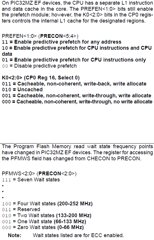
So there we get the value 0b11 for PREFEN, which means we want prefetch enabled for anything and everything, the value 0b010 for `PFMWS', meaning we want two wait states and the value 0b011 for the final configuration, which is the cache.
    cp0 = _mfc0(16, 0);
    cp0 &= ~0x07;
    cp0 |= 0b011; // K0 = Cacheable, non-coherent, write-back, write allocate
    _mtc0(16, 0, cp0);
Look at that mess. Why isn't there an easy way to do this? I don't know to be honest :) But this is how we access the CP0 (System Control Coprocessor) register number 16 which has the settings for the caching. In the data sheet, it looks like this:
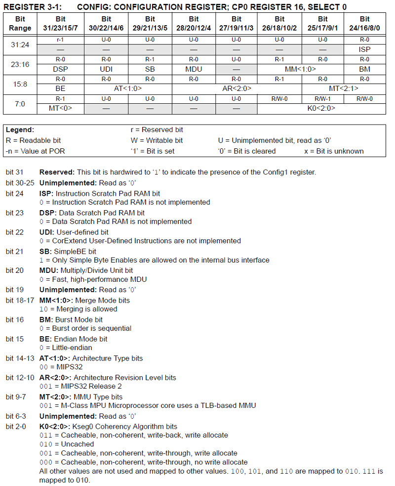
The last 3 bits of this CONFIG register are first set to 0 by going cp0 &= ~0x07;, which is saying cp0 = cp0 AND 11111111111111111111111111111000. We do this to only clearly the last 3 bits and leave the rest as is (very important to not mess up other configuration settings). Then we can set those last 3 bits to 0b011 by simply ORing them in. A look at the above image shows that 0b011 means Cacheable, non-coherent, write-back, write allocate. Which is basically telling the cache module to turn off any and all verification and to just work as fast as it possibly can. You can play around with the values if weird stuff is happening or you're doing something critical but for all of my projects the setting has been fine.
Finally, lock the settings back up again by writing some other number to the SYSKEY register and re-enable interrupts. Phew.
Here's the code
Categories: pic32